
Guided reamer system for reshaping bone

a reamer and bone technology, applied in the field of surgical tools, can solve the problems that the tool itself obstructs the view of the bone lobe, and achieves the effect of reducing friction and accurate and controlled reshaping of the bulbus bone join

Active Publication Date: 2011-04-05
VIANT AS&O HLDG LLC
View PDF19 Cites 14 Cited by
  • Summary
  • Abstract
  • Description
  • Claims
  • Application Information

AI Technical Summary

Benefits of technology

"The invention is a reamer system that can accurately and control the reshaping of the bulbus bone joint in preparation for the reception of a prosthetic cap. The system includes a cannulated reamer handle and a corresponding cannulated reamer. The reamer is made up of a cutting form and a central guide which supports a bar structure. The bar structure includes portions that connect to and extend radially from the central guide. The central guide has an offset surface to prevent the cutting form from plunging so far over the bone as to potentially damage the bulbus bone stem. The invention is a combination inverted reamer that reduces surgical time and increases accuracy. The cutting teeth have a lower cutting torque, allowing for a cut on multiple simultaneous surfaces. The system enables controlled cutting and reshaping of the bulbus bone joint while not damaging it in the process. The device can closely receive a bulbus bone joint prosthetic cap."

Problems solved by technology

Other systems provide for reshaping of the bone, but the tool itself generally obstructs the view of the bone lobe during cutting.
Such an application presents other challenges in guidance and control, particularly that of ensuring that the stem of the bulbus bone joint is not damaged in the process.

Method used


Image

  • Guided reamer system for reshaping bone
  • Guided reamer system for reshaping bone
  • Guided reamer system for reshaping bone

Examples


Embodiment Construction

)

[0023]Referring now to the drawings, the details of preferred embodiments of the present invention are graphically and schematically shown. Like elements in the drawings are represented by like numbers, and any similar elements are represented by like numbers with a different lower case letter suffix.

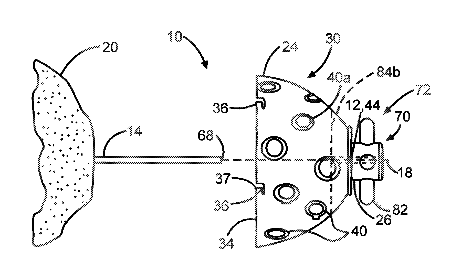
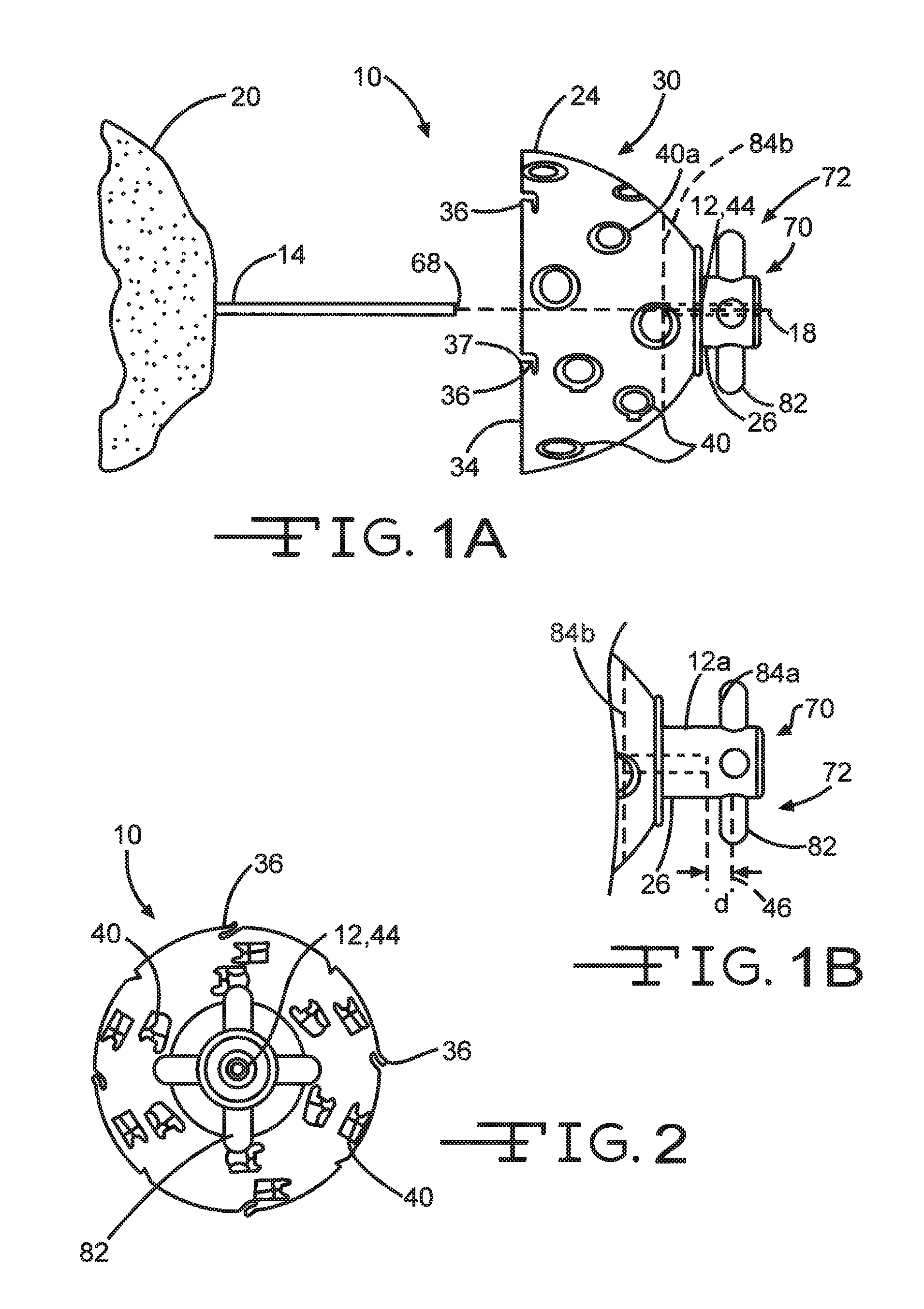
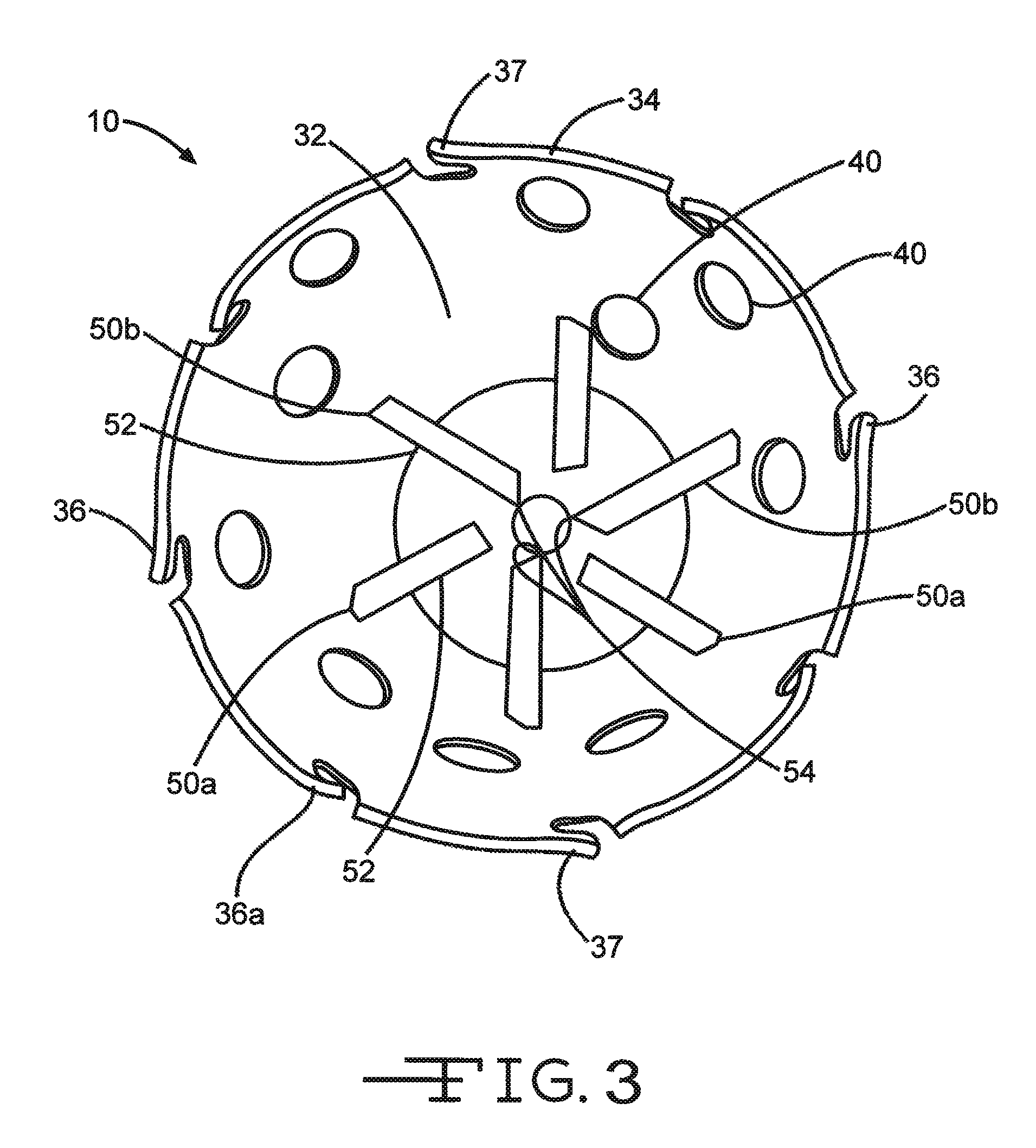
[0024]As shown in FIGS. 1A and 1B and FIGS. 2 to 3, the cannulated reamer 10 has a central guide bore (cannula) 12, 12a adapted to receive a guide or drill pin 14 secured in an appropriate manner in the femur or humerus bone joint 20 (preferably in a manner axially aligned with the stem 22 shown in FIG. 5A). In a preferred embodiment, the present reamer 10 is assembled in combination with a reamer handle (see FIGS. 4A-4C). The combination reamer handle and reamer head 10 is operable over a guide pin 14 affixed securely to the joint 20 usually by torquing into a pre-drilled hole. The guide pin 14 is axially aligned with reamer head 10 in an appropriate orientation with the joint 20. The...


PUM


Abstract

A guided reamer (10) has a central cannulation (12, 12a) adapted to receive a drill pin (14) secured in a manner which is axially aligned with the stem (22) of the bulbus bone joint (20). The reamer (10)has a profile cutting form (24) with cutting teeth (40) formed therein for cutting a form of a defined profile. The reamer (10) has a circumferential rim (34) having rim cutting teeth (36) disposed to cut to an outside of the rim and an inside of the rim, having face cutting teeth (37) adapted to cut an annular channel into bone and a plurality of planing teeth (52) radially disposed on an internal surface adjacent an axial end boss (44). The cannulation (12, 12a) is supported at the apex of the cutting form (24) and is formed in a guide assembly (70, 70′) affixed to the apex. The guide assembly (70, 70′) is adapted for imparting rotation to the reamer (12). The reamer (10) is adapted to be supported by a cannulated reamer handle (74) having a bayonet locking device (76) capable of locking the handle (74) to the guide assembly (70, 70′) of the cannulated reamer (10) and a corresponding central cannulation (86), permitting the drill pin (14) to pass at least part way therethrough.

Description

CROSS REFERENCE TO RELATED APPLICATIONS[0001]This application is a continuation-in-part application of U.S. application of the same name, Ser. No. 11 / 117,740, filed 29 Apr. 2005 and U.S. application Ser. No. 10,266,442, entitled ACETABULAR REAMER, filed Oct. 8, 2002, and claims priority under the Paris Convention to U.S. provisional applications entitled Inverted Reamer with Rim Cutting Teeth, Ser. Nos. 60 / 783,788 and 60 / 783,921, filed on Mar. 17, 2006 and Mar. 20, 2006, respectively, the contents of all of which are incorporated herein by reference and relied upon.BACKGROUND OF THE INVENTION[0002]The present invention is in the field of surgical devices for use in preparing a bone site for receiving a prosthesis. More specifically, the present invention relates to surgical tool head attachable to a surgical instrument holder.[0003]The invention relates to a bone shaping system made up of an instrument holder and a surgical instrument, i.e., a surgical tool head, for attachment to t...

Claims


Application Information

Patent Timeline
Patent Type & Authority Patents(United States)
IPC IPC(8): A61B17/00
CPCA61B17/1668A61B17/1684A61B17/175
Inventor GUELAT, DIDIERLECHOT, ANDRE
Owner VIANT AS&O HLDG LLC
Learn More