Method of improving sensor detection of target molcules in a sample within a fluidic system

a fluidic system and sensor technology, applied in the field of microfluidics, can solve the problems of false positives, techniques have their own drawbacks, and tasks are made more difficul

Inactive Publication Date: 2011-04-05
ADVANCED LIQUID LOGIC
View PDF13 Cites 136 Cited by
  • Summary
  • Abstract
  • Description
  • Claims
  • Application Information

AI Technical Summary

Benefits of technology

[0032]By achieving automated and precisely timed droplet manipulation at the chip level, far more repeatable and abundant data can be obtained as compared to manual pipette-based sample and reagent loading methods which are prone to human errors. Further, these results and can be obtained at far less cost and with greater flexibility than robotically driven pipette loading methods which require standardized plate dimensions and loading points.

Problems solved by technology

This task is made more difficult because 1) the specific target biomolecules are almost always randomly distributed throughout the sample volume and not concentrated at the sensing site; 2) the presence of other non-target or non-specific molecules within the sample can degrade the sensor response, leading to either false positives or to masking target biomolecule detection in by background noise; and 3) the actual detection of captured target molecules may require application of secondary markers and / or reaction substrates to the sensor.
These methods are currently used in biosensor, lab-on-chip, micro-total-analysis, microarray and other microfluidic applications; however each of these techniques has its own drawbacks.
Concentration can also fail when some or all of the target molecules are not sufficiently charged to be concentrated by electrophoresis and / or lack characteristics to be concentrated by the affinity method employed.
However, to circulate or agitate the entire sample volume, cumbersome seals, valving and costly mechanical, pneumatic, or surface acoustic wave methods are typically required.
Such complexity would likely impede application of such techniques to systems including numerous and / or highly distributed biosensors.
Unfortunately, leaky valving, air bubbles in channels, variations in capillary wetting characteristics and even differences in manual loading of samples and reagents often compromise precision timing of microfluidic delivery of such reaction solution(s).

Method used


Image

  • Method of improving sensor detection of target molcules in a sample within a fluidic system
  • Method of improving sensor detection of target molcules in a sample within a fluidic system
  • Method of improving sensor detection of target molcules in a sample within a fluidic system

Examples


Embodiment Construction

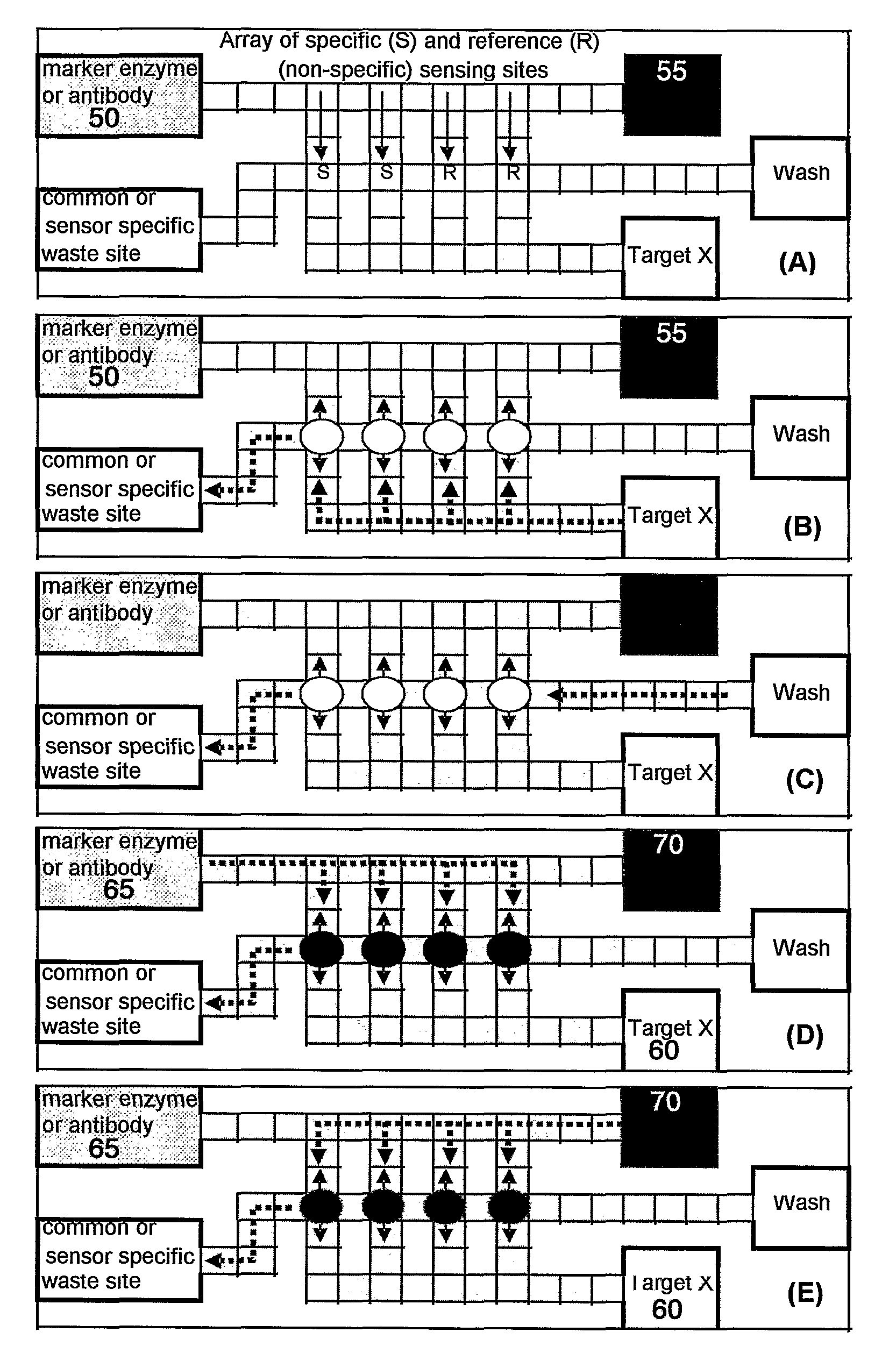
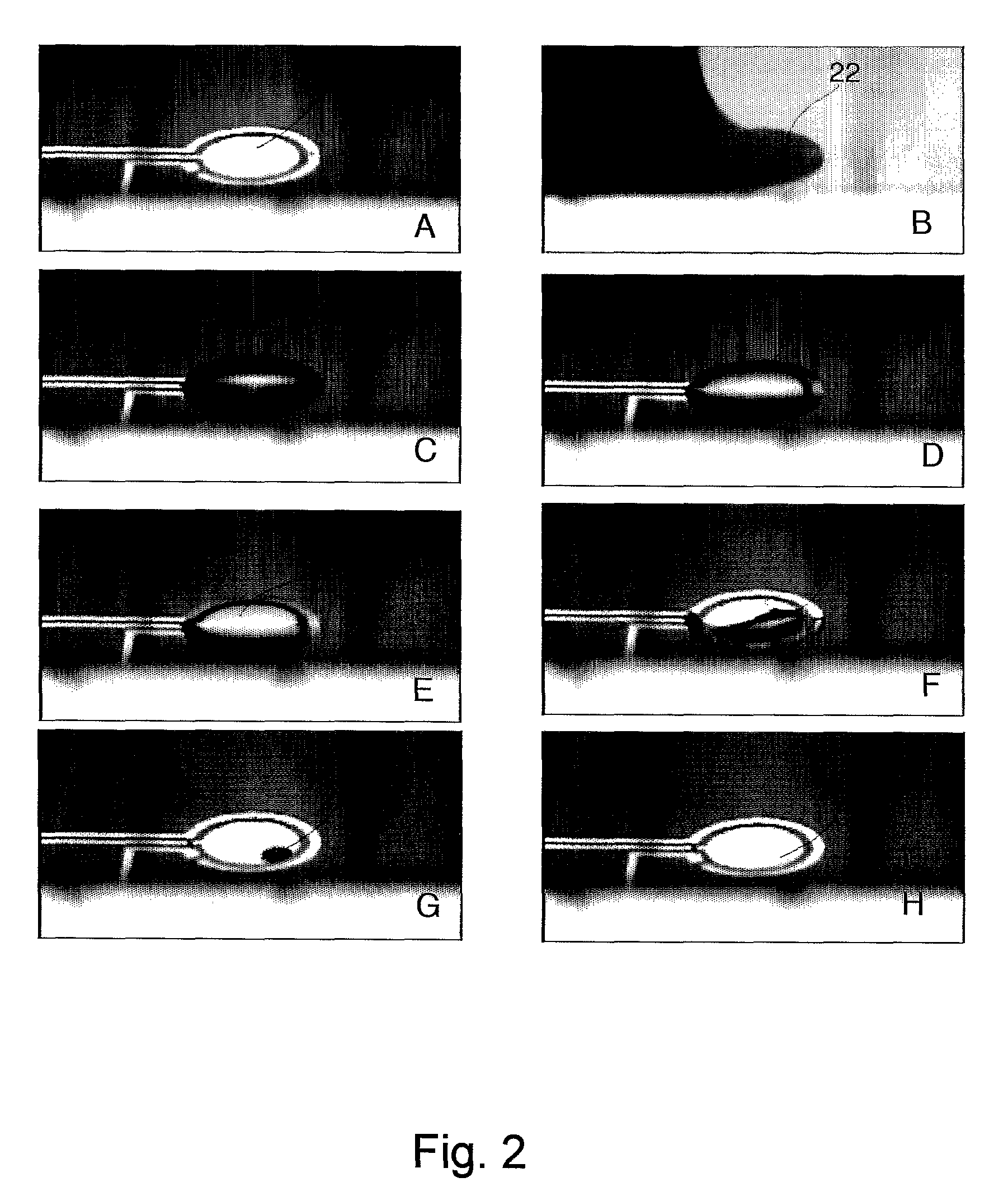
[0015]The present invention solves these and related problems by circulating the entire sample over the sensing site not as a continuous stream, but rather as a series of discrete, moving droplets which can be exposed, agitated, or even concentrated through evaporation at the sensor in a repeated and well-defined and repeatable manner (timing of delivery and exposure, frequency of agitation, degree of evaporation, number of repeat passes, periodic washing, etc). Such a discrete series of moving droplets can be achieved by using a variety of mechanical, electronic, chemical, optical or other droplet handling methods. One example of such on-chip discrete droplet control is the microfluidic handling capability achieved via Electro-Wetting-On-Dielectric (EWOD) effects [see 1) J. Lee, H. Moon, J. Fowler, T. Schoelihammer and C.-J. Kim, “Electrowetting and Electrowetting-On-Dielectric for Microscale Liquid Handling”, Sensors and Actuators, Vol. A95, 2002, pp. 259-268 and 2) S.-K. Cho, H. ...


PUM

PropertyMeasurementUnit
speedsaaaaaaaaaa
speedaaaaaaaaaa
diameteraaaaaaaaaa

Abstract

Methods of improving microfluidic assays are disclosed. Assays can be improved (better signal to noise ratio) by using sessile drop evaporation as an analyte concentration step (enhanced signal) and repeated passes of wash droplets as a means to reduce non-specific binding (noise reduction). In addition multiple massively parallel analyses improve the statistical precision of the analyses.

Description

CROSS-REFERENCE TO PRIOR APPLICATIONS[0001]The present applications claims the benefit of U.S. Provisional Application 60 / 691,073 filed on Jun. 16, 2005; the contents of which are incorporated by reference to the extent permitted by law.GRANT INFORMATION[0002]This invention was made with government support under DMI-0320082 awarded by the National Science Foundation. The government has certain rights in the invention.BACKGROUND OF THE INVENTION[0003]1. Area of the Art[0004]The present invention concerns the art of microfluidics—namely the transporting and processing of microliter—volume fluid samples. More specifically, this invention addresses the problem of improving biosensor detection by processing the sample volume in the form of discrete mobile droplets which can then be agitated, evaporated or driven over one sensor or a plurality of sensors.[0005]2. Description of the Prior Art[0006]A key performance criterion of many biosensors is their ability to detect low concentrations ...

Claims


Application Information

Patent Timeline
Patent Type & Authority Patents(United States)
IPC IPC(8): G01N33/558
CPCB01F13/0071B01F13/0076B01L3/502792G01N33/54373B01L2200/0605B01L2200/0678Y10T436/10B01L2300/0627B01L2300/0816B01L2400/0427Y10T436/25B01L2200/10B01F33/3031B01F33/3021
Inventor DE GUZMAN, PETER PATRICKLIU, WAYNE PO-WENYI, UICHONG BRANDONKIM, CHANG-JIN
Owner ADVANCED LIQUID LOGIC
Why Eureka
Try Eureka