
Surgical retractors and method of operation

a technology for retractors and heart surgery, applied in the field of retractors for heart surgery, can solve the problems of increased mortality from heart disease, rapid and disorganized heartbeat, and increased risk of stroke, and achieves the effects of reducing the risk of strok

Inactive Publication Date: 2011-04-12
GILLINOV ALAN MARC +1
View PDF25 Cites 26 Cited by
  • Summary
  • Abstract
  • Description
  • Claims
  • Application Information

AI Technical Summary

Benefits of technology

"The present invention provides improved surgical retractors and a technique for performing heart surgery, particularly atrial fibrillation reduction surgery. The retractors are designed to provide better access to the heart tissues and are particularly useful in the Maze procedure. The retractors have a unique design that allows for precise placement and retraction of the heart tissues, resulting in improved surgical outcomes. The invention also includes a method for performing an open-heart surgical procedure using the improved retractors."

Problems solved by technology

Instead of electrical impulses traveling in an orderly fashion through the heart, many impulses begin and spread through the atria, causing a rapid and disorganized heartbeat.
While it once was thought that atrial fibrillation was harmless, it now is known that atrial fibrillation is associated with heart failure, blood clots, a five- to sevenfold increase in stroke, and increased mortality from heart disease.
Unfortunately, non-surgical procedures such as pulmonary vein isolation ablation are not suitable to correct atrial fibrillation in all cases.
Unfortunately, manual retraction is quite undesirable for a number of reasons, including the need for the continual presence of an assistant to manipulate the retractor, and the inconsistency and variability of the retraction so provided.
The retractor blades are not properly configured to retract the heart tissues to perform the Maze procedure.
Placing and setting each of the blades takes a certain amount of time.

Method used


Image

  • Surgical retractors and method of operation
  • Surgical retractors and method of operation
  • Surgical retractors and method of operation

Examples


first embodiment

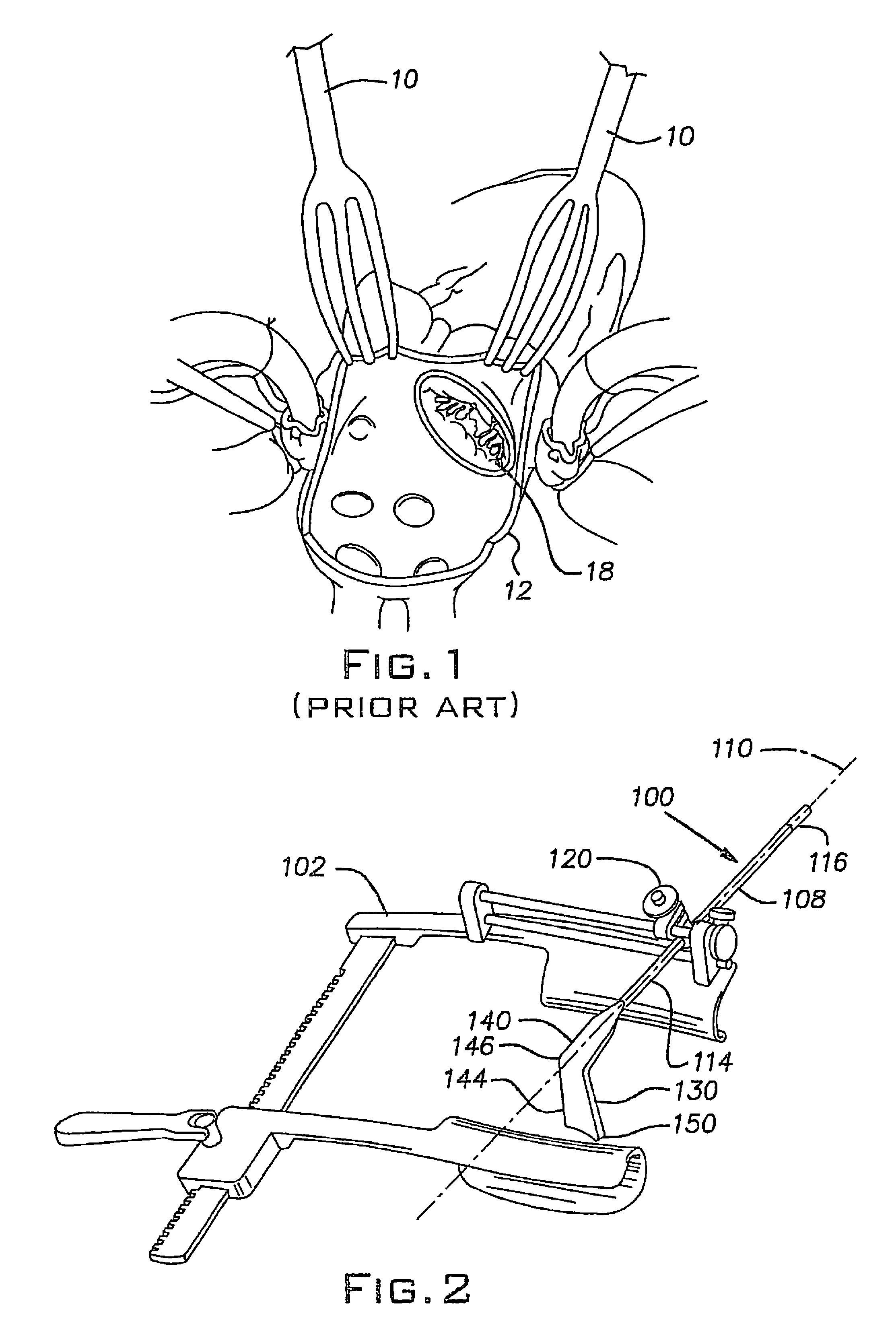
[0032]A surgical retractor 100 comprising the present invention is shown in FIG. 2. The retractor 100 is a mitral valve retractor adapted for use with a thoracic retractor 102. Suitable thoracic retractors are commercially available from Kapp Surgical Instrument, Inc. (Cleveland, Ohio). The retractor 100 in accordance with the present invention is operable to retract and expose, for example, a mitral heart valve (not shown) and the inside cavity of a heart during an open-heart surgical procedure. A Maze procedure is an example of such an open-heart surgical procedure. The retractor 100 differs from the prior art generally in that it is configured to contact the mitral valve and optionally the adjacent heart tissues rather than the heart wall's inner surface.

[0033]Specifically, the retractor 100 includes a 0.6 centimeter (0.25 inch) diameter surgical stainless steel rod or handle 108, which defines a handle axis 110. The handle 108 has first and second ends 114, 116. The handle secon...

second embodiment

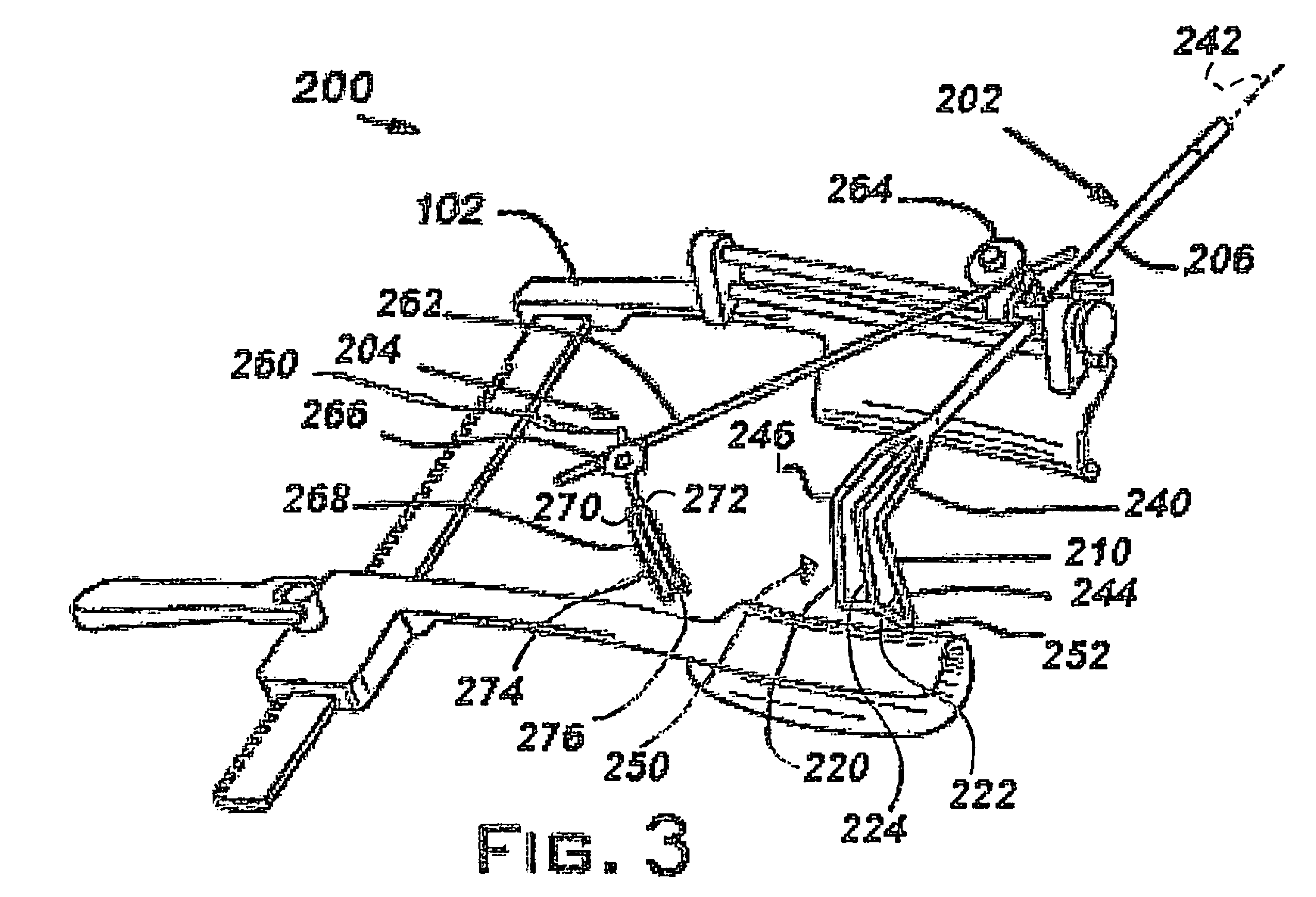
[0037]A retractor system 200 having first and second retractors 202, 204 and comprising the invention is shown in FIG. 3. The first retractor 202 has a handle 206 and a blade 210. The blade 210 differs from the solid blade 130 by including a plurality of spokes (preferably a first spoke 220, a second spoke 222, and a middle, third spoke 224).

[0038]The blade 210 is formed of a malleable metal and defines a proximal portion 240 that is generally co-planar with a handle axis 242, which is defined by the handle 206. The blade 210 further defines a distal portion 244 that is angled relative to the handle axis 242. A first bend 246 defines a boundary between the proximal and distal portions 240, 244. The spokes 220, 222, 224 of the distal portion 244 are thus also angled relative to the handle axis 242. The first and second spokes 220, 222 each have a second bend 250 so that the first and second spokes 220, 222 are about equal distances away from the center spoke 224 in generally opposite...

third embodiment

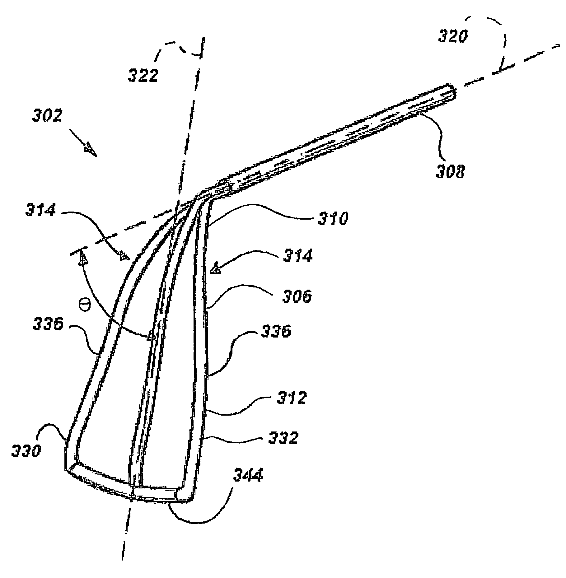
[0048]A retractor system 300 comprising the invention is shown in FIGS. 4-8. The retractor system 300 includes first and second retractors 302, 304.

[0049]The first retractor 302 includes a blade 306 mounted to a handle 308. The blade 306 has proximal and distal portions 310, 312 that are defined by a bend 314. The proximal and distal portions 310, 312 together measure about 19 cm (7.5 inches) long. The proximal portion 310 is centered on a handle axis 320, which is defined the handle 308. A clamp 322 releaseably secures the handle 308 to the thoracic retractor 102.

[0050]The distal portion 312 includes first, second and third spokes 330, 332, 334 that preferably have a length in a range of about 12 cm (4.75 inches) to about 13.3 cm (5.25 inches) long and are about 0.3 cm (0.1 inch) wide. The spokes 330, 332, 334 extend in generally straight lines from the first bend 314 at the intersection of the proximal and distal portions 310, 312 to a tip 344 at the opposite end of the distal por...


PUM


Abstract

A first surgical retractor (302) according to the invention includes a handle (308) that defines an axis (320) and has first and second ends. A retractor blade (306) is secured to the second end of the handle. The blade is of a size and shape to engage the mitral valve of a heart so as to be able to retract the mitral valve and adjacent tissues. A second retractor (304) according to the invention has a relatively narrow, elongate blade (352) that can extend deep into the heart to engage the heart in the region of the atrial appendage so as to be able to retract the atrium and expose the pulmonary veins. The retractors are especially adapted to perform an atrial fibrillation surgical procedure.

Description

REFERENCE TO RELATED APPLICATION[0001]This application claims priority to provisional Patent Application Ser. No. 60 / 377,929, filed May 3, 2002, by A. Marc Gillinov and Albert N. Santilli, the disclosure of which is hereby incorporated by reference in its entirety.BACKGROUND OF THE INVENTION[0002]1. Field of the Invention[0003]The present invention relates generally to retractors for use in heart surgery and, more particularly, to retractors for use during open-heart surgery.[0004]2. Description of the Prior Art[0005]The heart is a hollow muscular pump located in the chest cavity in a loose protective sack called the pericardium. The heart is comprised of a thick muscular layer called the myocardium, which defines four chambers that include two upper chambers, the atria, and two lower chambers, the ventricles. The atrium and ventricle on the right side are separated by a tricuspid valve, while the atrium and ventricle on the left side are separated by a bicuspid (mitral) valve. The ...

Claims


Application Information

Patent Timeline
Patent Type & Authority Patents(United States)
IPC IPC(8): A61B1/32A61B17/02
CPCA61B17/02A61B2017/0237A61B17/0206
Inventor GILLINOV, ALAN MARCSANTILLI, ALBERT N.
Owner GILLINOV ALAN MARC
Learn More