Constant current source mirror tank dimmable ballast for high impedance lamps

a technology of dimmable ballast and constant current source, which is applied in the direction of light sources, basic electric elements, instruments, etc., can solve the problems of lamp flicker, ballast cannot control the current to the lamp, and the dimmable ballast of the prior art has difficulty in dimming multiple energy efficient gas discharge lamps. achieve the effect of stable and balanced operation

Inactive Publication Date: 2011-04-12
UNIVERSAL LIGHTING TECHNOLOGIES
View PDF10 Cites 4 Cited by
  • Summary
  • Abstract
  • Description
  • Claims
  • Application Information

AI Technical Summary

Benefits of technology

[0007]To control the current to at least two high-impedance gas discharge lamps, first and second ballast circuits are connected effectively in parallel to an inverter circuit. Each of these ballast circuits has a resonant circuit which is connectable to a high impedance lamp. Each resonant circuit is a third-order resonant circuit or higher. Consequently, the transfer function for each of these resonant circuits has at least three poles. In one embodiment, each third-order resonant circuit has a resonant inductor, a resonant capacitor, and a ballast capacitor which is connected in series with the resonant inductor and capacitor. By appropriately selecting the reactance of these components, the ballast provides stable and balanced operation to the high impedance lamps.
[0009]In addition, an end of life protection circuit may be connected to each resonant circuit to receive an end of life signal. These end of life signals are received and transmitted to an end of life circuit in the inverter. This is needed because if the end of life signal is set for full power operation, the ballast would shutdown when the lamp was dimmed due to the dramatic rise in the voltage of the lamp when dimming. The end of life protection circuit is preferably connected to an input terminal on the resonant capacitor. Voltage sensing circuits receive end of life signals from both resonant circuits and diodes add the end of life signals. This permits an end of life circuit in the inverter circuit to function properly.

Problems solved by technology

However, prior art dimmable ballast have difficulty dimming multiple energy efficient gas discharge lamps due to the high impedance of these lamps when operated at dimming power levels.
Consequently, the ballast is unable to control the current to the lamps due to the high leakage currents to ground.
This results in lamp flicker and makes it difficult to start the lamp if ambient temperatures are low (below 20 C.°) or when the lamp leads are extended greater than 5 feet.
Also, multiple high impedance lamps may present an unbalanced load to the power source.
In these situations, prior art lamp ballasts have been unable to balance the current between the lamp loads.

Method used


Image

  • Constant current source mirror tank dimmable ballast for high impedance lamps
  • Constant current source mirror tank dimmable ballast for high impedance lamps
  • Constant current source mirror tank dimmable ballast for high impedance lamps

Examples


Embodiment Construction

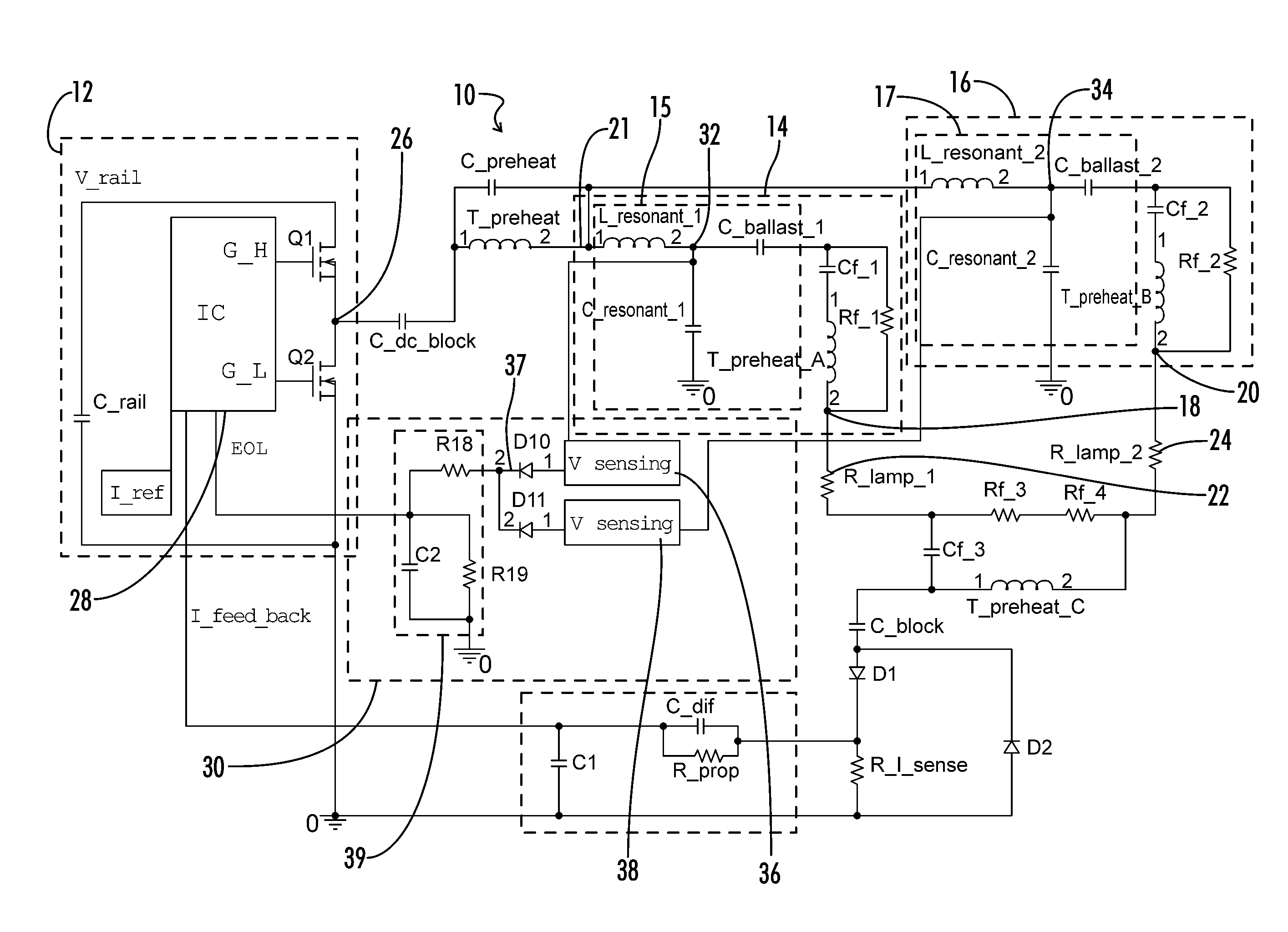
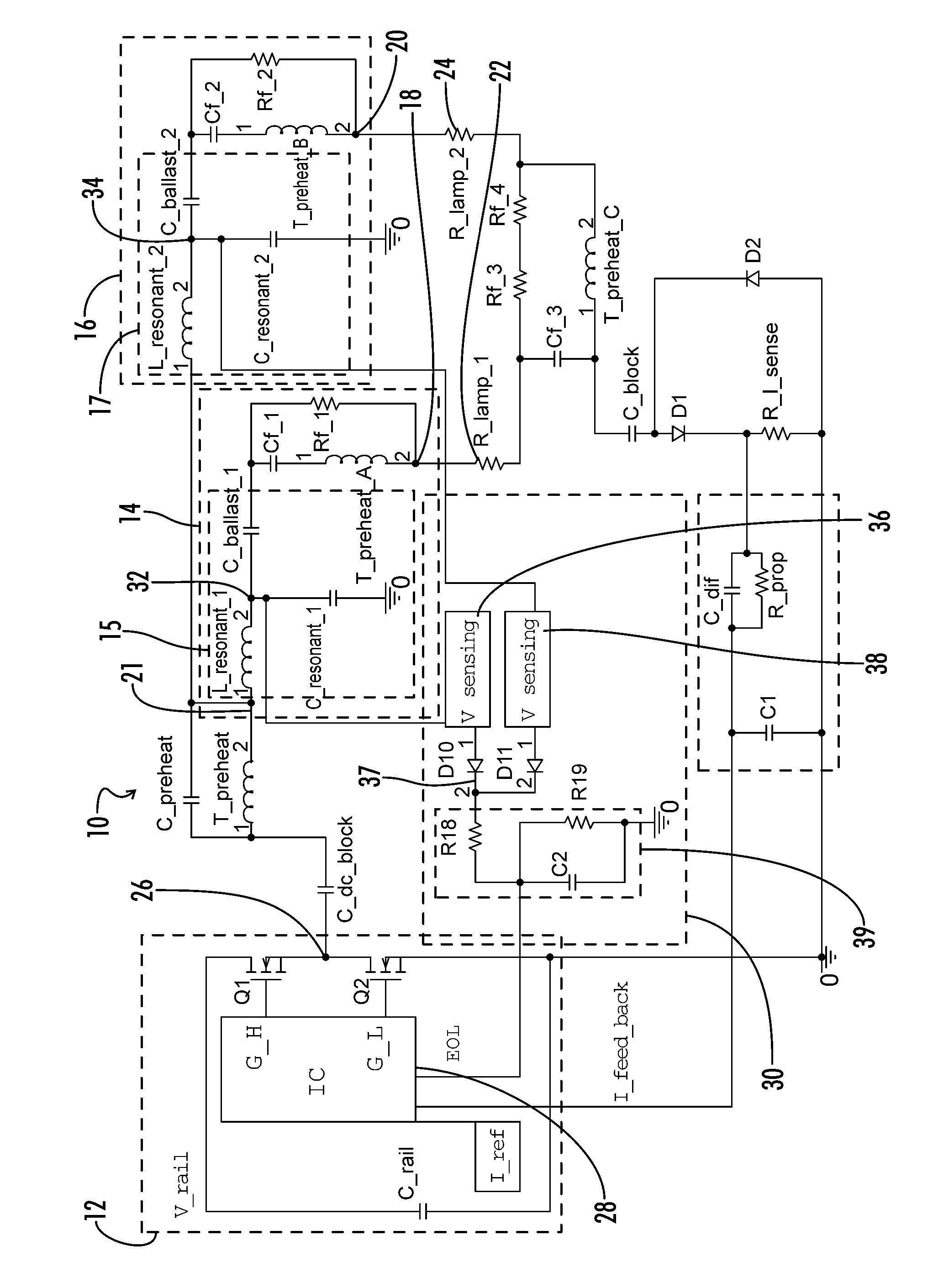
[0011]The basic topology of a preferred embodiment of the electronic ballast 10 in accordance with the invention is shown in the Drawing. An inverter 12 is coupled to first and second ballast circuits 14, 16. The inverter 12 and the ballast circuits 14, 16 convert a DC voltage, V_rail, into an AC signal of the appropriate voltage and frequency for powering high impedance gas discharge lamps. By varying the switching frequency of the switches Q1, Q2 in the inverter circuit 12, the resultant AC signal powers the gas-discharge lamps at either a normal power level or at a dimming power level. A DC blocking capacitor can be placed between the inverter output terminal 26 and the ballast circuits 14, 16 to block any DC components.

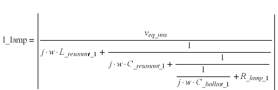
[0012]Each of these ballast circuits 14, 16 has a third-order resonant circuit 15, 17. The resonant circuits 15, 17 are designed in such a way that the current flow through the lamp impedances R_lamp—1, R_lamp—2 is nearly constant. Each resonant circuit 15, 17 may...


PUM


Abstract

A constant current source mirror tank dimmable ballast operates multiple high impedance lamps in a stable and balanced manner. The dimmable ballast has an inverter connected to two third-order resonant circuits. These third-order resonant circuits dominate the transfer function of the ballast circuits. Consequently, changes in the impedance of the lamp do not affect the current output to the lamps.

Description

CROSS-REFERENCES TO RELATED APPLICATIONS[0001]This application is a non-provisional application which claims benefit of U.S. patent application Ser. No. 60 / 988,926 filed Nov. 19, 2007, entitled “A CONSTANT CURRENT SOURCE MIRROR TANK DIMMABLE BALLAST FOR HIGH IMPEDANCE LAMP” which is hereby incorporated by reference.BACKGROUND OF THE INVENTION[0002]The present invention relates generally to electronic ballasts for gas discharge lamps. More particularly, this invention pertains to a dimmable ballast that operates multiple high impedance lamps in a stable and balanced manner.[0003]Dimmable ballasts have gained popularity due to their ability to control the illumination level of gas discharge lamps. For example, dimmable ballasts may be designed to power lamps at both a dimming power level and a normal power level. This ability to control the power output to the lamp increases the energy efficiency of a facility utilizing gas-discharge lamps to light a space.[0004]Facilities also save e...

Claims


Application Information

Patent Timeline
Patent Type & Authority Patents(United States)
IPC IPC(8): H05B37/02
CPCH05B41/42Y10S315/04
Inventor XIONG, WEILUNN, THOMASRADZINSKI, CHRISTOPHER
Owner UNIVERSAL LIGHTING TECHNOLOGIES
Why Eureka
Try Eureka