Magnet unit, elevator guiding apparatus and weighing apparatus

a technology of guiding apparatus and magnet unit, which is applied in the direction of elevators, magnetic bodies, instruments, etc., can solve the problems of reducing the stability of the elevator car in its equilibrium situation, reducing the stability of the elevator guiding apparatus adopting the above magnet unit or the like, and accompanied by great electric power consumption, so as to reduce the deviation of attraction forces, reduce the capacity of a power source, and enhance the controllability of the respective magnetic pole

Inactive Publication Date: 2011-04-12
TOSHIBA ELEVATOR KK
View PDF25 Cites 11 Cited by
  • Summary
  • Abstract
  • Description
  • Claims
  • Application Information

AI Technical Summary

Benefits of technology

[0022]In the above-mentioned situation, it is an objective of the present invention to provide a magnet unit that can accomplish a reduction of deviations of attraction forces of permanent magnets due to the directions of the magnetic forces and can enhance their controllability to respective magnetic poles, thereby allowing a reduction in the capacity of a power source. Another objective of the invention is to provide an elevator guiding apparatus and the like having such a magnet unit and operates stably with high efficiency.
[0024]With the above configuration of both the first magnet and the second magnet, a deviation in magnetic paths from each permanent magnet up to respective magnetic poles of the magnet unit is reduced, and fluxes (or flux densities) at respective magnetic poles can be controlled individually.
[0025]That is, since the directional deviation in the attraction forces of the permanent magnets is reduced with an improvement in the controllability of the exciting currents to respective magnetic poles, it is possible to provide a magnet unit which is well-balanced in operation and further stable in both responsibility and controllability in operation.
[0030]In each of above weighing apparatuses, as the control unit controls the exciting currents of the magnet unit based on output signals from the sensors, there can be attained, between the guide member and the magnet unit, appropriate attraction forces and controllability both having small deviations in directions, allowing the weight of the object to be measured stably and effectively.

Problems solved by technology

Since these guide devices guide the elevator car with being in contact with the guide rails directly, these guide devices are predisposed to generate vibrations and noises due to distortion and connections of the guide rails, so such vibrations and noises are easily propagated into the elevator car though rollers and the like.
In the case of adopting the magnet unit 1 in the elevator guiding apparatus, however, the stability of an elevator car in its equilibrium situation is damaged due to the above difference of attraction force in between the backward-and-forward direction (i.e. the direction y) and the left-and-right direction (i.e. the direction x).
Accordingly, an elevator guiding apparatus adopting the above magnet unit (s) or the like has a reduced stability in operation since both responsibility and controllability of the magnets are different from each other depending on the directions.
However, this measure is accompanied with great electric power consumption, requiring a capacious power source.

Method used


Image

  • Magnet unit, elevator guiding apparatus and weighing apparatus
  • Magnet unit, elevator guiding apparatus and weighing apparatus
  • Magnet unit, elevator guiding apparatus and weighing apparatus

Examples


first embodiment

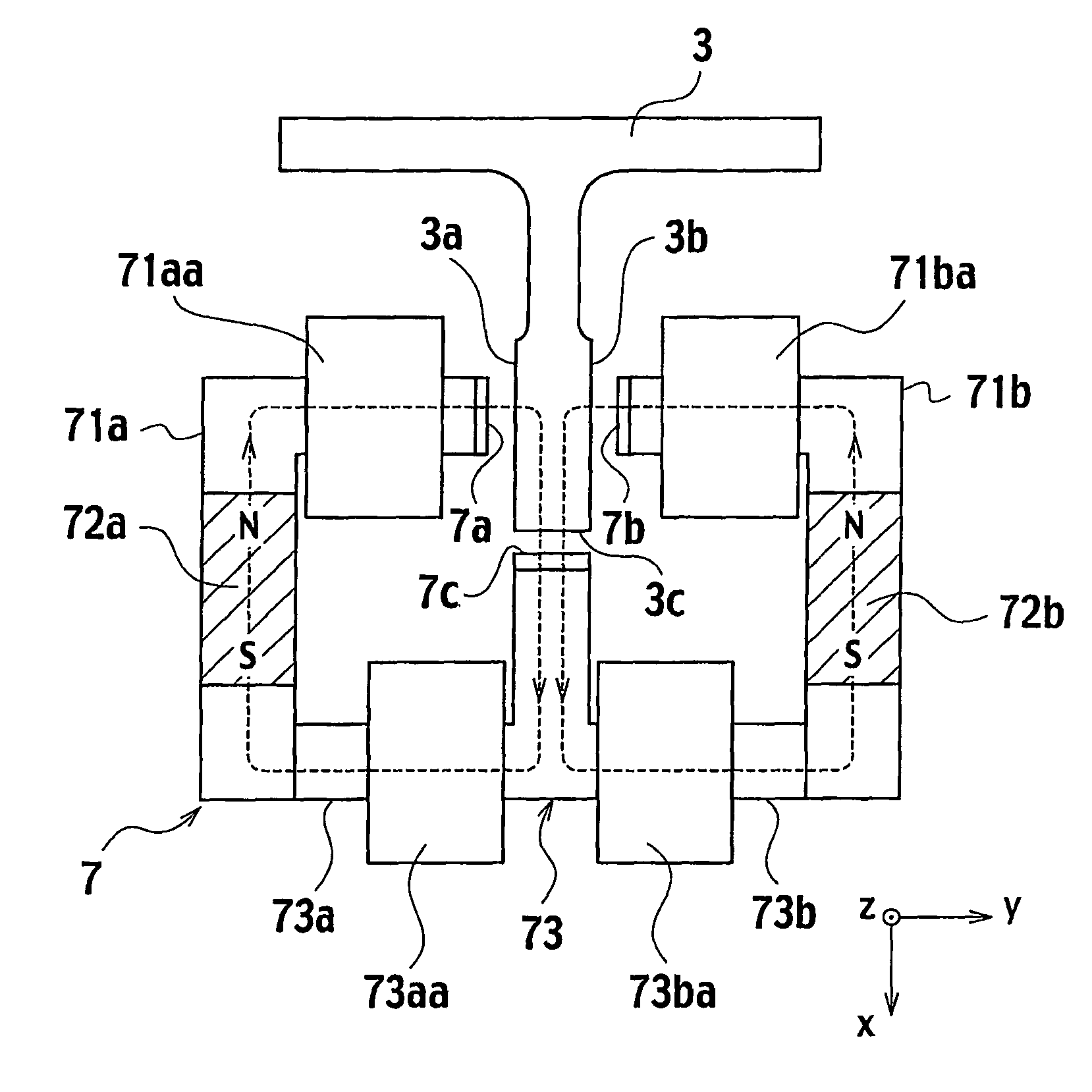
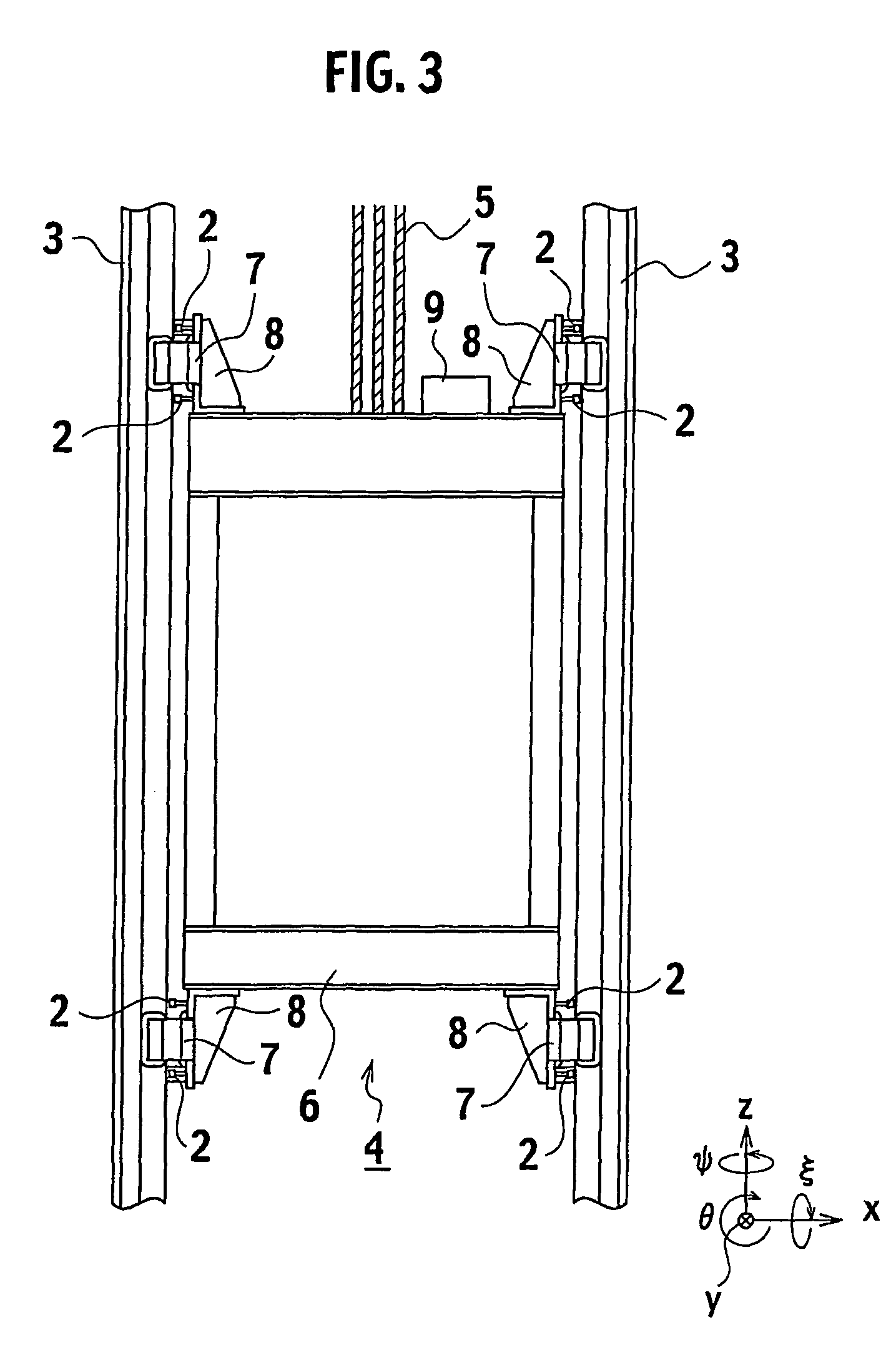
[0068]As obvious from above, on condition of adopting the above-mentioned magnet unit 7 of the first embodiment as the elevator guiding apparatus and further installing four units 7 to four (up, down, left and right) corners of the elevator car 6 through the pedestals 8 together with the sensors 2 while opposing the guide rails 3, the control of exciting currents to the respective electromagnets allows, the elevator car 6 to be posture-controlled to a translational direction (i.e. x-y directions) in the horizontal plane and a rotational direction (i.e., ξ, θ, φ directions), whereby non-contact and stable guide control of the elevator car 6 to the guide rails 3 can be accomplished.

[0069]FIG. 7 is a structural view of a circuit of the elevator guiding apparatus provided by adding a controller to the magnet unit 7 of the first embodiment and the sensors 2. Thus, the elevator guiding apparatus includes the electromagnets 71a, 71b, 73a, 73b of the magnet unit 7, the sensors 2 for detecti...

second embodiment

[0076]The second embodiment where the center electromagnet 73 of the magnet unit 7 is formed by the single electromagnet will be described with reference to FIG. 8.

[0077]As shown in this figure corresponding to FIG. 8 of the first embodiment, an electromagnet 73c is arranged at a projecting part of the third pole 7c of the center electromagnet 73 to form a magnetic circuit (magnetic path) in common with the permanent magnets 72a, 72b.

[0078]Similar to the first embodiment, a magnetic path between the permanent magnet 72a and its pole is substantially equal to that between the permanent magnet 72b and its pole. Thus, while a difference in the attraction force between the directions becomes small, by controlling the exciting currents to the respective electromagnets 71a, 72b, 73c based on the sensors 2 in the adoption of the elevator guiding apparatus, it is possible to control attraction forces in both directions x and y individually, allowing the elevator car 6 to be controlled betw...


PUM

PropertyMeasurementUnit
polarityaaaaaaaaaa
magneticaaaaaaaaaa
magnetic polesaaaaaaaaaa

Abstract

A magnet unit includes a first magnetic pole (7a), a second magnetic pole (7b) and a third magnetic pole (7c) at a center between the first magnetic pole (7a) and the second magnetic pole (7b), providing an E-shaped configuration. In the magnet unit, a first magnet is defined between the first magnetic pole (7a) and the third magnetic pole (7c) by connecting two electromagnets (71aa, 73aa) with each other through a permanent magnet (72a), while a second magnet is defined between the second magnetic pole (7b) and the third magnetic pole (7c) by connecting two electromagnets (71ba, 73ba) with each other through a permanent magnet (72b). With this configuration, it is possible to reduce a deviation in the length of respective magnetic paths from the permanent magnets (72a, 72b) up to their respective magnetic poles. By controlling exciting currents to the respective magnetic poles. By controlling exciting currents to the respective electromagnets (71aa, 73aa, 71ba, 73ba), it is also possible to adjust fluxes (or flux density) in respective directions x, y individually.

Description

TECHNICAL FIELD[0001]The present invention relates to the improvement of a magnet unit that is preferred to an elevator guiding apparatus and the like.BACKGROUND ART[0002]In an elevator, generally, guide rails are arranged in pairs on an elevator shaft vertically. Being guided by these guide rails, an elevator car suspended by a main rope moves up and down the elevator shaft.[0003]In order to allow the elevator car to be guided along the guide rails, a guide device is mounted on a car frame of the elevator car.[0004]There are a roller-type guide device and a guide shoe-type guide device. Since these guide devices guide the elevator car with being in contact with the guide rails directly, these guide devices are predisposed to generate vibrations and noises due to distortion and connections of the guide rails, so such vibrations and noises are easily propagated into the elevator car though rollers and the like.[0005]Thus, an elevator guiding apparatus that adopts a magnet unit for th...

Claims


Application Information

Patent Timeline
Patent Type & Authority Patents(United States)
IPC IPC(8): H01F7/08H02K41/02H01F7/00B66B1/06B66B1/34B66B7/02B66B7/04B66B11/02G01G7/02G01G19/18
CPCB66B1/3476G01G19/18G01G7/02B66B7/044B66B7/00B66B7/02B66B7/04G01G7/00
Inventor ITO, HIROAKIMORISHITA, MIMPEITONAMI, YOSUKE
Owner TOSHIBA ELEVATOR KK
Why Eureka
Try Eureka