
Isolation magnetic devices capable of handling high speed communications

a magnetic device and isolation magnetic technology, applied in the direction of magnets, continuously variable inductance/transformers, magnetic bodies, etc., can solve the problems of inability to physically handle the magnetizing force of prior art magnetic devices, voltage imbalance will generate current imbalance,

Active Publication Date: 2011-04-12
BEL FUSE MACAO COMML OFFSHORE
View PDF9 Cites 15 Cited by
  • Summary
  • Abstract
  • Description
  • Claims
  • Application Information

AI Technical Summary

Benefits of technology

The solution effectively handles higher signal speeds up to gigabits per second while maintaining compatibility with conventional RJ45 formats, providing improved isolation and reduced parasitic capacitive coupling, thus addressing the limitations of prior art devices.

Problems solved by technology

Such offsets may be caused by various factors including imbalances in the wires of the plug.
Although there is still a net difference across the pair of wires of +5 volts (which may, for example, correspond to a logic “1”), such a voltage imbalance will generate a current imbalance.
However, prior art magnetic devices cannot physically handle the magnetizing force which may be induced by imbalanced current having high frequencies.
The above prior art isolation magnetic device generally does not have the frequency response characteristic needed to inhibit the presence of DC current bias with communications of such speeds.
Even for solutions which are capable of handling high speed (e.g. 2M bits per second) communications, they typically are not backward compatible (i.e. they cannot handle slower communications) and are frequently not in a conventional RJ45 type connector format.

Method used


Image

  • Isolation magnetic devices capable of handling high speed communications
  • Isolation magnetic devices capable of handling high speed communications
  • Isolation magnetic devices capable of handling high speed communications

Examples


Embodiment Construction

)

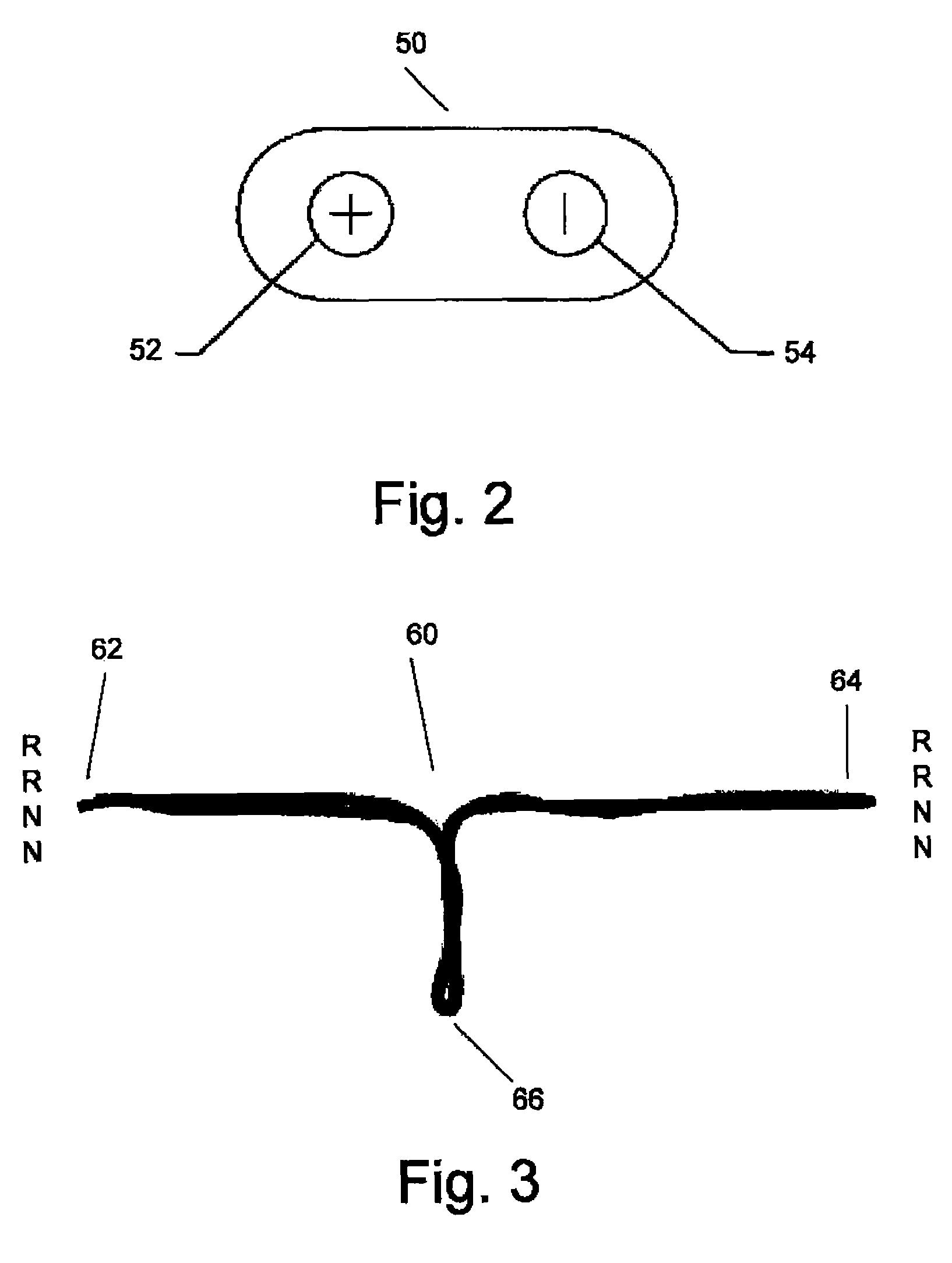
[0023]Referring now to the drawings wherein like reference numerals describe identical or corresponding parts throughout the several views, and more particularly to FIG. 2, a core 50 is shaped substantially like an ellipsoid with its ends cut off and has a substantially racetrack-shaped cross-section. Core 50 includes a first hole 52 and a second hole 54. Core 50 may have, for example, a material permeability of between 1500 and 5000 and size dimensions as shown in FIG. 2A or 2B. For example, for the size dimensions shown in FIG. 2A, core 50 may be made with chamfered tooling and tumbled to remove sharp edges. Under a first test condition, at 100 KHz, B=5 G, u(Ref.)=5000, AL=5638.7 nH / N2±30% with a loss factor of −6. The core may be coated overall with Parylene C to 0.0005″-0.0010″. Dimensions may beprior to the coat and the core may be ROHS compliant. For the size dimensions shown in FIG. 2B, core 50 may be manufactured with flat faced tooling with a pre-sintered edge rounding pr...


PUM

PropertyMeasurementUnit
distanceaaaaaaaaaa
voltage imbalanceaaaaaaaaaa
distanceaaaaaaaaaa

Abstract

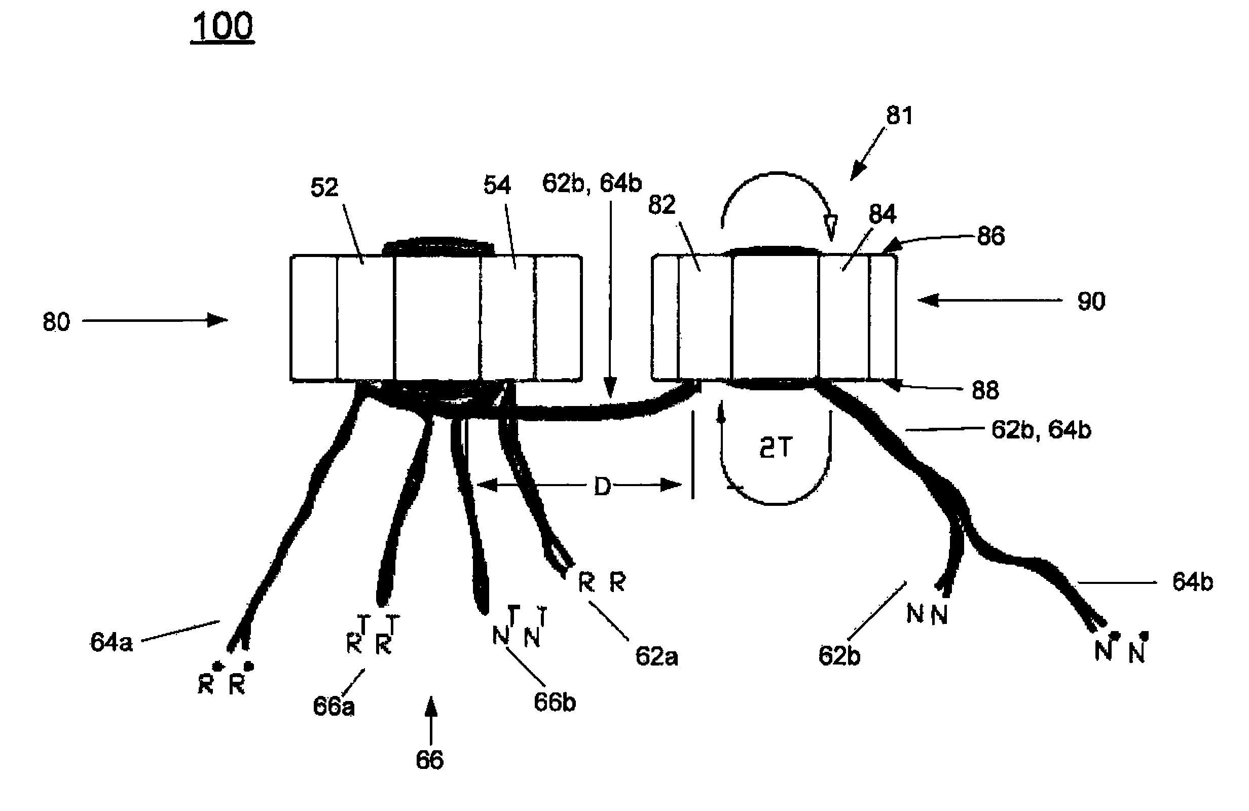
An isolation magnetic device produced by inserting a first end of a wire through a first hole of a core, wrapping the first end of the wire around a first side of the core and inserting the first end of the wire through a second hole of the core. The second hole of the core is spaced from the first hole and has a longitudinal axis extending parallel to a longitudinal axis of the first hole. The device is further produced by inserting a second end of the wire through the second hole of the core, wrapping the second end of the wire around the first side of the core and inserting the second end of the wire through the first hole of the core.

Description

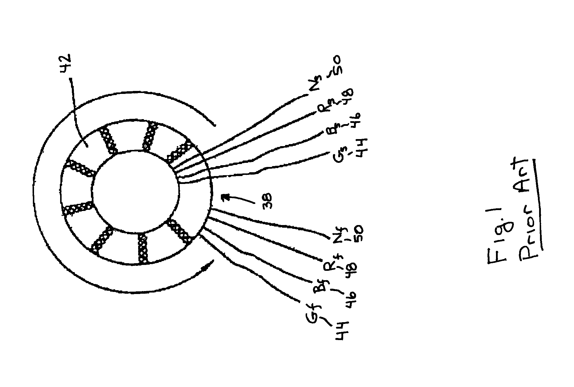
BACKGROUND OF THE INVENTION[0001]Regulations for connector technology are evolving. As signal speeds increase and the connector industry desires to move data faster over cables, there is a need for isolating magnetic devices capable of handling higher magnetizing forces and DC current bias. In a typical RJ45 type connector assembly where a modular plug mates in a male-female relationship with a modular jack, an isolating magnetic device is used in the female connector portion to handle direct current (“DC”) offsets. Such offsets may be caused by various factors including imbalances in the wires of the plug.[0002]For example, data is frequently transmitted over a pair of conductive wires. When transmitting data, the pair of wires may ideally have voltage potentials to ground such that a voltage in one wire of the pair is equal and opposite to the voltage in the other wire of the pair. For example, one wire may have a potential of −2.5 volts and the other wire may have a potential of ...

Claims


Application Information

Patent Timeline
Patent Type & Authority Patents(United States)
IPC IPC(8): H01F27/28H01F27/00H01F21/06H01F17/04H01F7/06
CPCH01F17/062H01F17/08H01F41/08Y10T29/49071H01F2017/067H01F19/08
Inventor BUCKMEIER, BRIAN J.HESS, JOHNBERRY, JOSEPHEDRALIN, EDWIN
Owner BEL FUSE MACAO COMML OFFSHORE
Learn More