
Method for sensing the presence of a human body part within a region of a machine tool

a technology of human body and machine tool, which is applied in the direction of instruments, slip couplings, couplings, etc., can solve the problem of not always possibl

Inactive Publication Date: 2011-04-12
BRUNSWICK CORPORATION
View PDF25 Cites 54 Cited by
  • Summary
  • Abstract
  • Description
  • Claims
  • Application Information

AI Technical Summary

Benefits of technology

[0030]A method of sensing the presence of a human body part within a predefined region of a machine tool, in accordance with a preferred embodiment of the present invention, comprises the steps of receiving a data signal which comprises one or more sensor values, identifying a first monitored zone within a viewed area, comparing each of the plurality of sensor values within the first monitored zone to a preselected color which is representative of the hu

Problems solved by technology

This is not always possible.

Method used


Image

  • Method for sensing the presence of a human body part within a region of a machine tool
  • Method for sensing the presence of a human body part within a region of a machine tool
  • Method for sensing the presence of a human body part within a region of a machine tool

Examples


Embodiment Construction

[0045]Throughout the description of the preferred embodiment of the present invention, like components will be identified by like reference numerals.

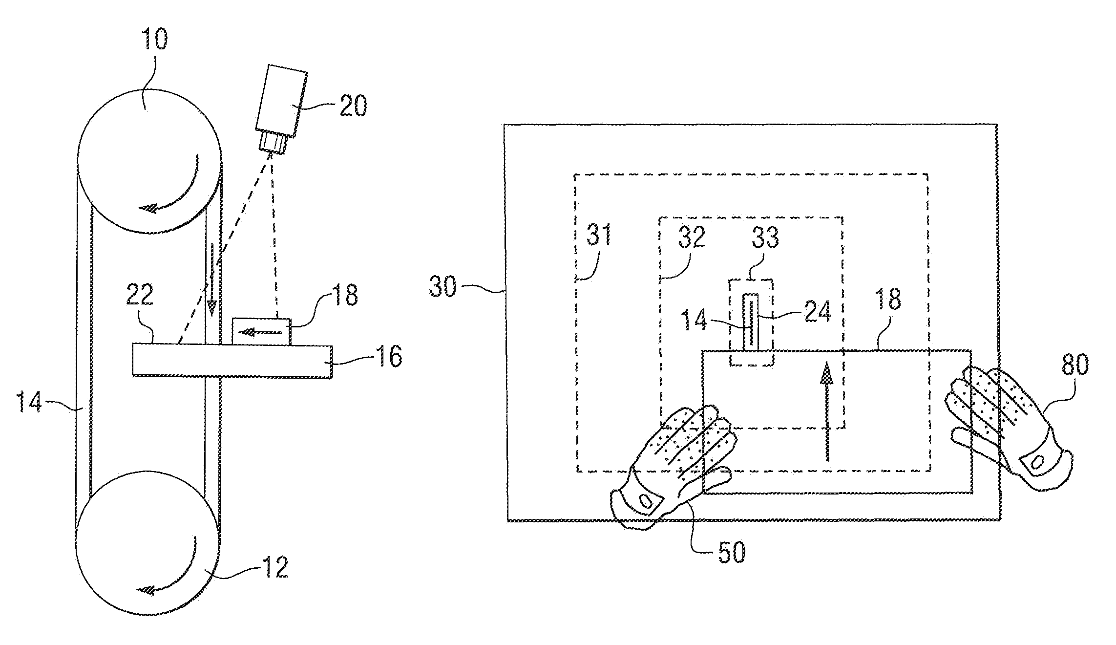
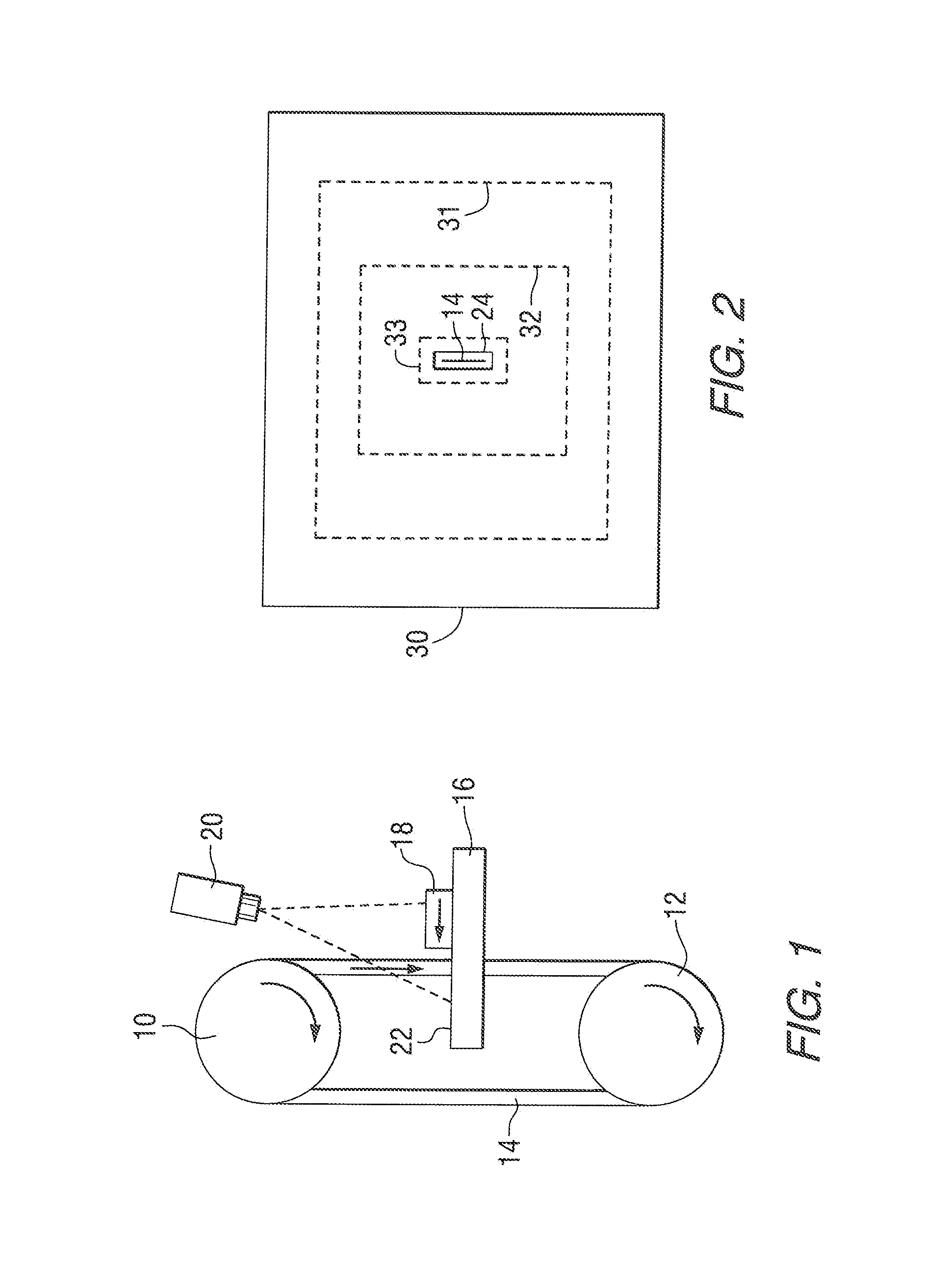
[0046]FIG. 1 is a simplified schematic representation of a band saw which comprises two rotating wheels, 10 and 12, and a continuous cutting band 14. The band 14 extends through an opening in a support table 16 on which a work piece 18 can be maneuvered so that it is cut by the band. The rotating wheels, 10 and 12, the band 14, and the work piece 18 are movable in the directions represented by the arrows in FIG. 1. In one embodiment of the present invention, a camera 20 is positioned above the upper surface of the table 16 and directed downwardly to view a portion of that upper surface 22.

[0047]With reference to FIGS. 1 and 2, FIG. 2 shows the viewed area 30 within the observation range of the camera 20. The band 14 extends through an opening 24 formed in the upper surface 22 of the table 16. The dashed line rectangles in FIG. 2 represe...


PUM


Abstract

A detection system senses the location of a preselected color within one or more monitored zones of a machine tool. If the operator of a machine tool wears a red glove, the system detects the location of the color red and defines various monitored zones through the use of synchronization signals and a time circuit. The system can take action based on the location of the particular monitored zones in which the red glove is sensed. These actions can include the sounding of a horn, the lighting of a light, or the deactivation of the machine tool.

Description

BACKGROUND OF THE INVENTION[0001]1. Field of the Invention[0002]The present invention is generally related to a method for avoiding injury to the operator of a machine tool and, more particularly, to a method which detects a preselected color representing a human body part within one or more zones proximate a potential cause of injury.[0003]2. Background of the Invention[0004]Those skilled in the art of the design, manufacture, and use of machine tools are aware of many different techniques used to reduce the likelihood of injury to the operator of the machine tool. These techniques include many different types of sensors, shields, and barriers, which are intended to prevent various body parts from moving into contact with injury causing components of the machine tool.[0005]U.S. Pat. No. 4,249,074, which issued to Zettler et al. on Feb. 3, 1981, describes an intrusion detector for a press brake. The system is intended for safeguarding an operator of an industrial machine such as a p...

Claims


Application Information

Patent Timeline
IPC IPC(8): G08B23/00
CPCF16P3/142
Inventor STAERZL, RICHARD E.
Owner BRUNSWICK CORPORATION
Learn More