Inkjet recording apparatus

a recording apparatus and inkjet technology, applied in the direction of printing, other printing apparatus, etc., can solve the problems of reducing increasing the manufacturing cost of apparatuses, and difficult to control variations in ink ejection characteristics over a wide temperature range, so as to reduce the yield of driver ics, reduce the manufacturing cost of apparatuses, and suppress the effect of ink ejection characteristics

Active Publication Date: 2011-04-19
BROTHER KOGYO KK
View PDF9 Cites 3 Cited by
  • Summary
  • Abstract
  • Description
  • Claims
  • Application Information

AI Technical Summary

Benefits of technology

[0008]An object of the present invention is to provide an inkjet recording apparatus in which variation in ink ejection characteristics has been suppressed over a broad temperature range.
[0009]Another object of the present invention is to provide a low-cost inkjet recording apparatus in which ink ejection characteristics scarcely vary even when the number of nozzles changes from which ink droplets are to be ejected at once.
[0013]As the number increases of pulse signals to be output at once from the plurality of waveform output circuits, the one or more variable resistance elements decrease in their resistance values. This decreases the time constants of the CR circuits constituted by the plurality of capacitors in the actuator unit and the one or more variable resistance elements. On the other hand, the increase in the number of pulse signals to be output at once from the plurality of waveform output circuits brings about an increase in the number of capacitors in the actuator unit to be activated by the pulse signals applied. This increases the time constants of the CR circuits constituted by the activated capacitors and the one or more variable resistance elements. As a result, the time constants of the CR circuits are prevented from widely varying. Conversely, as the number decreases of pulse signals to be output at once from the plurality of waveform output circuits, the one or more variable resistance elements increase in their resistance values. This increases the time constants of the CR circuits. On the other hand, the decrease in the number of pulse signals to be output at once from the plurality of waveform output circuits brings about a decrease in the number of capacitors in the actuator unit to be activated by the pulse signals applied. This decreases the time constants of the CR circuits constituted by the activated capacitors and the one or more variable resistance elements. As a result, also in this case, the time constants of the CR circuits are prevented from widely varying. Because the one or more variable resistance elements are thus changed in their resistance values so as to suppress the variations in the time constants of the CR circuits caused by a change in the number of nozzles to eject ink droplets at once, the ink ejection characteristics scarcely vary even when the number of nozzles to eject ink droplets at once is changed. In addition, for the use of components such as driver ICs including the plurality of waveform output circuits, it is not necessary to select only those in which the pulse voltages are within a predetermined range. This realizes the manufacture of apparatuses at low cost.

Problems solved by technology

Because a change in the viscosity of ink thus causes changes in ink ejection characteristics, including the ink ejection amount and the ink ejection velocity, it is difficult to control variations in the ink ejection characteristics over a wide temperature range.
However, this reduces the yield of driver ICs and thus increases the manufacturing cost of apparatuses.

Method used


Image

  • Inkjet recording apparatus
  • Inkjet recording apparatus
  • Inkjet recording apparatus

Examples


Embodiment Construction

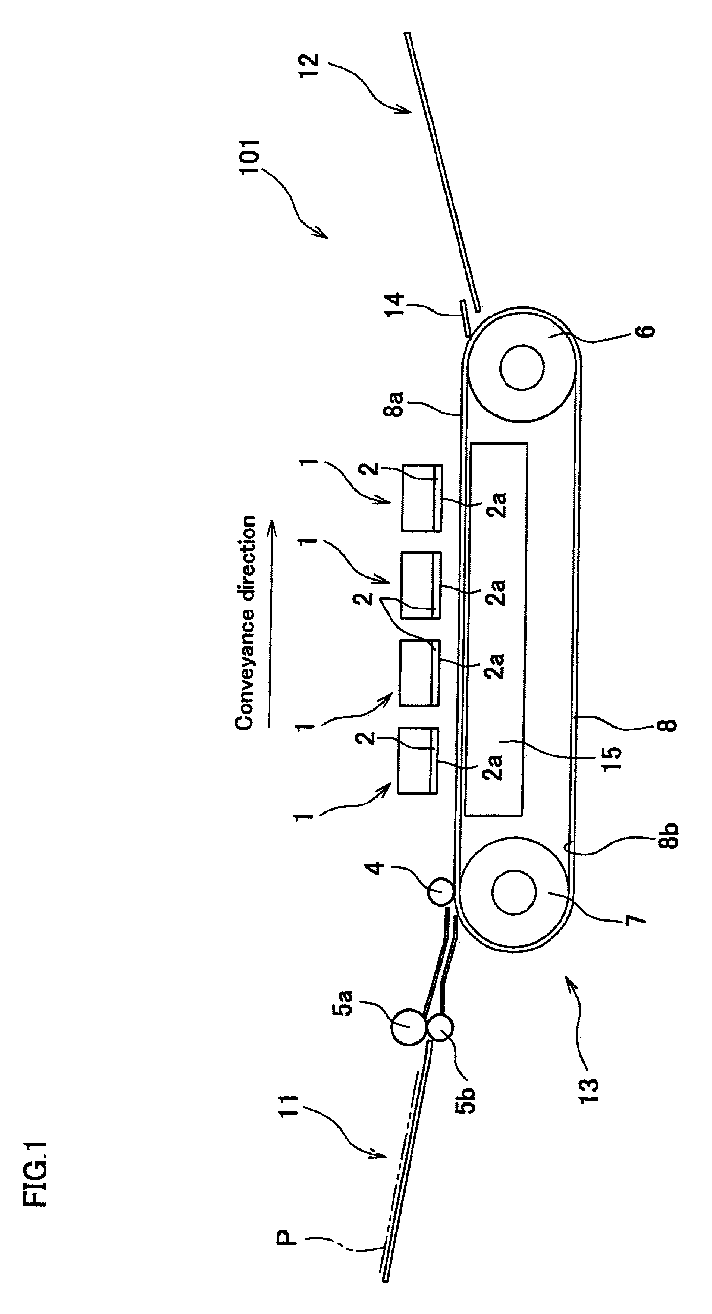
[0026]FIG. 1 shows an inkjet printer 101 according to an embodiment of the present invention. The inkjet printer 101 is a color inkjet printer having four inkjet heads 1 for respectively ejecting four different color inks of yellow, magenta, cyan, and black. The inkjet printer 101 includes a paper feed tray 11 in a left region in FIG. 1 and a paper discharge tray 12 in a right region in FIG. 1.

[0027]In the inkjet printer 101 formed is a conveyance path in which a paper P as a recording medium is conveyed from the paper feed tray 11 toward the paper discharge tray 12. At a position immediately downstream of the paper feed tray 11, a pair of feed rollers 5a and 5b are positioned for pinching the paper to convey. The pair of feed rollers 5a and 5b takes the paper P out of the paper feed tray 11 and sends the paper P rightward in FIG. 1. In the middle of the conveyance path, a belt conveyor mechanism 13 is provided that includes two belt rollers 6 and 7; an endless conveyor belt 8 wrapp...


PUM


Abstract

An inkjet recording apparatus includes a passage unit; an actuator unit including a plurality of individual electrodes; a plurality of waveform output circuits which output pulse signals to be supplied to the plurality of individual electrodes; one or more variable resistance elements connected to the actuator unit; a temperature sensor which detects environmental temperature; and a controller which controls the one or more variable resistance elements so that the one or more variable resistance elements decrease in their resistance values with a decrease in the environmental temperature detected by the temperature sensor.

Description

CROSS REFERENCE TO RELATED APPLICATION[0001]The present application claims priority from Japanese Patent Application No. 2007-8060, which was filed on Jan. 17, 2007, the disclosure of which is herein incorporated by reference in its entirety.BACKGROUND OF THE INVENTION[0002]1. Field of the Invention[0003]The present invention relates to an inkjet recording apparatus in which ink droplets are ejected to print.[0004]2. Description of Related Art[0005]An inkjet head included in an inkjet printer for printing on a recording medium by ejecting ink droplets includes a passage unit on which nozzles are formed for ejecting ink droplets and in which pressure chambers are formed which are connected to the respective nozzles; a piezoelectric actuator for giving ejection energy to ink in each pressure chamber; and a driver IC for outputting a driving signal to drive the piezoelectric actuator. The piezoelectric actuator serves to change the volume of each pressure chamber and thereby give press...

Claims


Application Information

Patent Timeline
Patent Type & Authority Patents(United States)
IPC IPC(8): B41J29/393
CPCB41J2/04541B41J2/04581B41J2/04568B41J2/04553
Inventor ITO, KOJI
Owner BROTHER KOGYO KK
Why Eureka
Try Eureka