Control apparatus for vehicular power transmitting system

a control apparatus and transmission system technology, applied in the direction of vehicle sub-unit features, process and machine control, propulsion parts, etc., can solve the problems of limiting the output torque to be transmitted to the drive wheels, excessive charging, and failure of the first electric motor to generate a sufficient reaction torque, so as to increase the ratio of the torque value received, prevent overcharging of the electric energy storage device, and increase the torque valu

Inactive Publication Date: 2011-04-19
TOYOTA JIDOSHA KK
View PDF4 Cites 35 Cited by
  • Summary
  • Abstract
  • Description
  • Claims
  • Application Information

AI Technical Summary

Benefits of technology

[0010]The control apparatus constructed according to the above-described mode (1) of the present invention comprises the torque-receiving-proportion control portion configured to control that the proportion of the torque values of the reaction torque corresponding to the torque acting on the predetermined member of the electrically controlled differential portion, which torque values are respectively received by the first electric motor and the coupling device, such that the ratio of the torque value received by the coupling device, with respect to the reaction torque, increases with an increase of the difference of the electric energy amount consumed by the second electric motor from the electric energy amount generated by the first electric motor. Accordingly, the ratio of the torque value received by the coupling device is increased as the above-indicated difference increases, that is, as the electric energy amount stored in the electric-energy storage device increases, so that the reaction torque received by the first electric motor is reduced, and the electric energy amount generated by the first electric motor is accordingly reduced, whereby the electric energy amount supplied to the electric-energy storage device is accordingly reduced. Thus, the balance between the charging and discharging amounts of the electric-energy storage device is suitably optimized so as to prevent overcharging of the electric energy-storage device, making it possible to prolong the expected service life of the electric-energy storage device.
[0022]In the above-described mode (7) of this invention, the ratio of the torque value received by the coupling device is increased when the charging amount of the electric-energy storage device per unit time exceeds the upper limit, for example. Accordingly, overcharging of the electric-energy storage device is prevented. When the discharging amount of the electric-energy storage device per unit time exceeds the upper limit, on the other hand, the ratio of the torque value received by the first electric motor is increased. Accordingly, overdischarging of the electric-energy storage device is prevented.

Problems solved by technology

In the power transmitting system for a hybrid vehicle as disclosed in the above-identified publication, the electric-energy storage device which is charged and discharged by the first and second electric motors can be charged with an electric energy generated by the first electric motor when the amount of electric energy stored in the electric-energy storage device is relatively small, but may be excessively charged if the electric energy generated by the first electric motor is supplied to the electric-energy storage device when the amount of electric energy stored in the electric-energy storage device is relatively large.
However, the limitation of the electric energy generated by the first electric motor results in a failure of the first electric motor to generate a sufficient reaction torque, and consequent limitation of an output torque to be transmitted to the drive wheels.
However, the amount of slipping of the coupling device should be rapidly increased if the slipping control of the coupling device is implemented immediately before the electric-energy storage device is excessively charged.
The rapid increase of the slipping amount may cause an overloading of the coupling device.

Method used


Image

  • Control apparatus for vehicular power transmitting system
  • Control apparatus for vehicular power transmitting system
  • Control apparatus for vehicular power transmitting system

Examples


Embodiment Construction

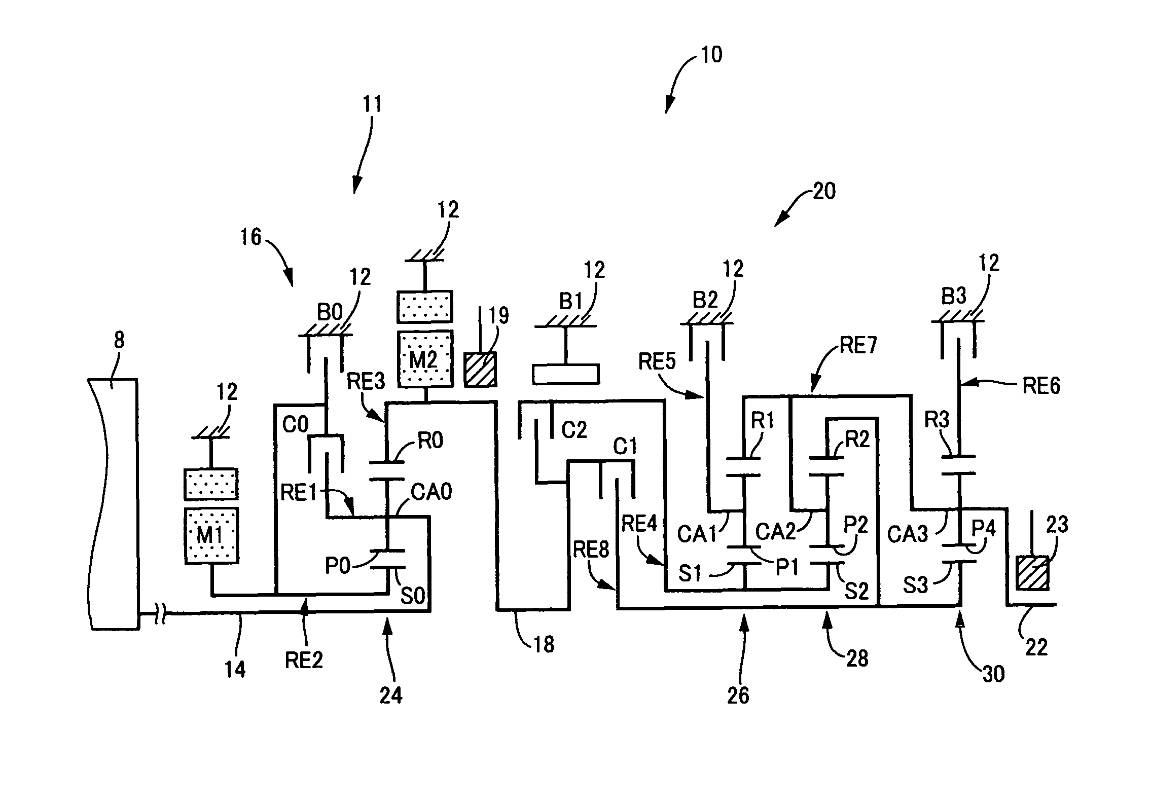
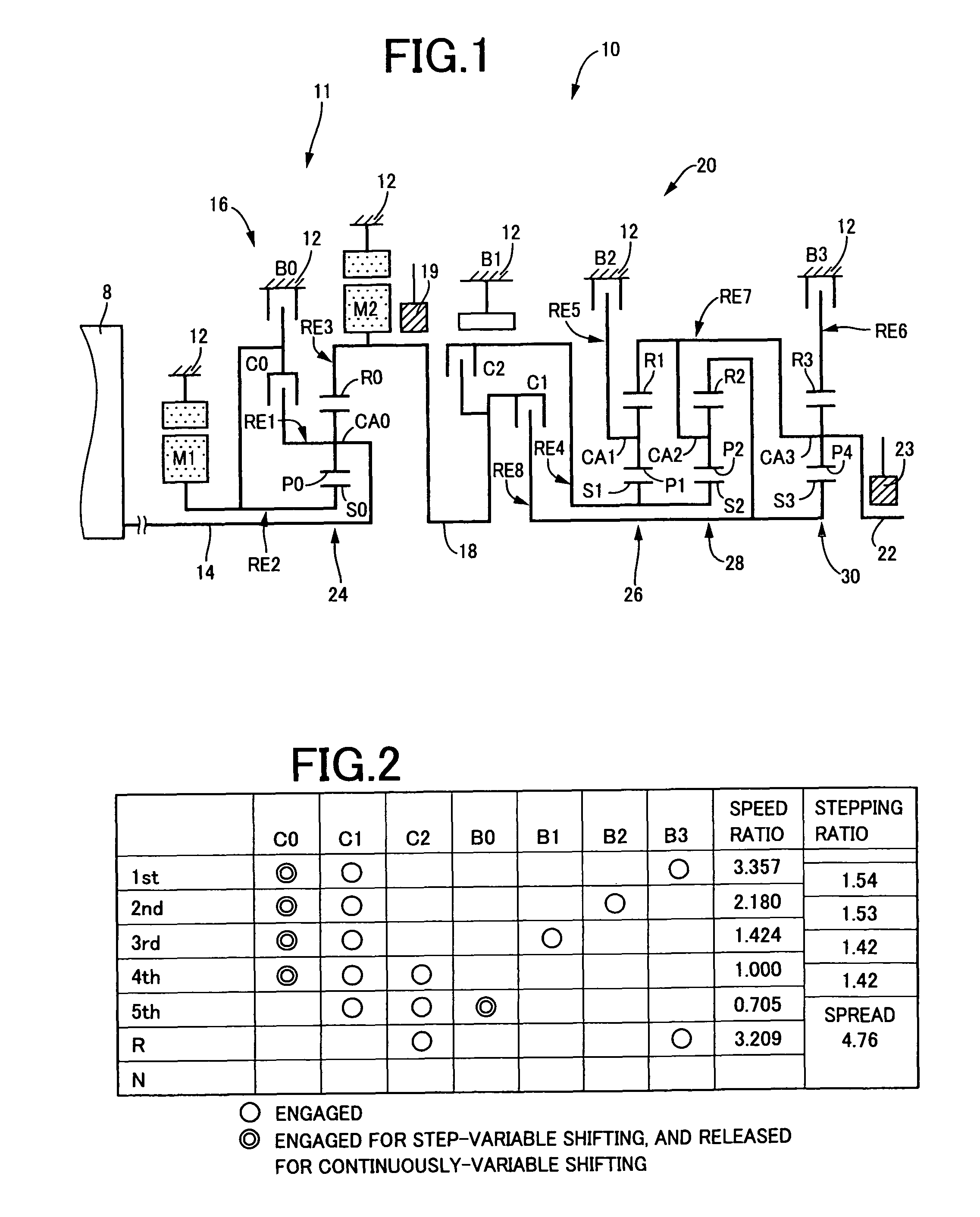
[0040]Referring to the schematic view of FIG. 1, there is shown a transmission mechanism 10 constituting a part of a power transmitting system for a hybrid vehicle, which power transmitting system is controlled by a control apparatus according to one embodiment of this invention. In FIG. 1, the transmission mechanism 10 includes: an input rotary member in the form of an input shaft 14; a differential portion 11 connected to the input shaft 14 either directly, or indirectly via a pulsation absorbing damper (vibration damping device) not shown; a step-variable or multiple-step transmission portion in the form of an automatic transmission portion 20 disposed between the differential portion 11 and drive wheels 38 (shown in FIG. 6) of the vehicle, and connected in series via a power transmitting member 18 (power transmitting shaft) to the differential portion 11 and the drive wheels 38; and an output rotary member in the form of an output shaft 22 connected to the automatic transmission...


PUM


Abstract

A control apparatus for a vehicular power transmitting system including (a) an electrically controlled differential portion operable to distribute an output of a drive power source of a vehicle to a first electric motor and a power transmitting member, (b) a second electric motor connected to a power transmitting path between an output shaft of the drive power source and a drive wheel of the vehicle, (c) a coupling device provided in the electrically controlled differential portion and operable to selectively switch the differential portion between a differential state and a non-differential state, and (d) an electric-energy storage device operable to store and discharge an electric energy supplied from the first or second electric motor, the control apparatus including a torque-receiving-proportion control portion configured to control a proportion of torque values of a reaction torque corresponding to a torque acting on a predetermined member of the electrically controlled differential portion, which torque values are respectively received by the first electric motor and the coupling device, such that a ratio of the torque value received by the coupling device, with respect to the reaction torque, increases with an increase of a difference of an electric energy amount consumed by the second electric motor from an electric energy amount generated by the first electric motor.

Description

[0001]The present application claims priority from Japanese Patent Application No. 2007-285103 filed on Nov. 1, 2007, the disclosure of which is herein incorporated by reference in its entirety.BACKGROUND OF THE INVENTION[0002]1. Field of the Invention[0003]The present invention relates in general to a control apparatus for a vehicular power transmitting system including an electrically controlled differential portion operable to distribute an output of a drive power source to a first electric motor and a power transmitting member, and a second electric motor connected to a power transmitting path between an output shaft of the drive power source and a drive wheel of a vehicle, and more particularly to techniques for optimizing a balance between an amount of charging of an electric-energy storage device with an electric energy generated by the first electric motor and an amount of electric energy of the electric-energy storage device consumed by the second electric motor.[0004]2. Di...

Claims


Application Information

Patent Timeline
Patent Type & Authority Patents(United States)
IPC IPC(8): B60K1/02B60K6/365B60K6/445B60K6/547B60K17/04B60L15/20B60W10/02B60W10/08B60W10/10B60W10/26B60W20/00F16H61/00F16H63/50
CPCB60K6/445B60K6/547B60W10/06B60W10/08B60W10/115B60W20/00B60K6/365B60K1/02Y10T477/23B60L2240/421B60L2240/423B60L2240/441B60L2240/445B60L2240/485B60L2240/486B60W2510/0638B60W2510/0676B60W2510/068B60W2510/0685B60W2510/081B60W2510/107B60W2510/244B60W2520/10B60W2520/105B60W2520/28B60W2530/10B60W2540/10B60W2540/12B60W2540/16B60W2710/0605B60W2710/0666B60W2710/083F16H3/728F16H2037/0873F16H2200/0047F16H2200/2012F16H2200/2048Y02T10/6286Y02T10/642Y02T10/7258Y02T10/6239B60Y2400/435F16H3/66F16H2200/201Y02T10/62Y02T10/64Y02T10/72B60W20/13B60W2510/242B60W2510/084
Inventor IMAMURA, TATSUYAIWASE, YUJITABATA, ATSUSHI
Owner TOYOTA JIDOSHA KK
Why Eureka
Try Eureka