Bone separator

a technology of bone separator and clamping screw, which is applied in the field of bone separator, can solve the problems of insufficient secureness of clamping screw, inability to maneuver, and difficulty in maneuvering, and achieve the effect of being especially simple and clear arrangemen

Active Publication Date: 2011-04-19
CERVITECH INC
View PDF14 Cites 70 Cited by
  • Summary
  • Abstract
  • Description
  • Claims
  • Application Information

AI Technical Summary

Benefits of technology

[0002]According to the invention, this disadvantage is remedied by the fact that the locking device is designed in the form of a locking finger which is guided between a locking position and a release position in a transverse movement tangentially with respect to the pin holder and at least one transverse groove in the pin, into which groove the locking finger engages in the locking position. Several transverse grooves may also be provided, one of which is chosen for the engagement of the locking finger. To ensure that the locking finger cannot be lost as a separate part, according to a further feature of the invention, it is designed as a hook which is mounted so as to be pivotable about an axis extending approximately parallel to the pin holder. The arrangement is especially simple and clear if the hook is arranged at the open end of the pin holder closer to the parallel guide system.

Problems solved by technology

For this purpose, a first known design of this locking device, disclosed in WO03 / 024344, uses a friction clamp, which in many cases is not secure enough.
A clamping screw, however, cannot be maneuvered, or may be maneuvered only with difficulty, deep within the operating site.
The issue remains, furthermore, of how a clamp can be designed so that it is both secure and easy to operate.

Method used


Image

  • Bone separator
  • Bone separator

Examples


Embodiment Construction

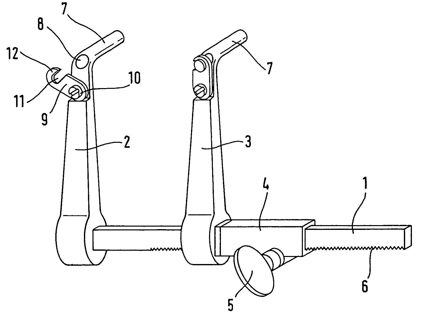
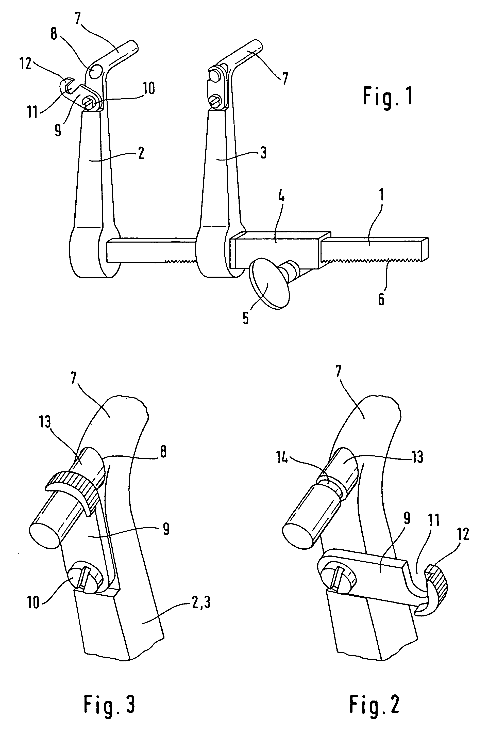
[0006]A first spreader body 2 is arranged rigidly at the end of a guide bar 1 of noncircular cross section. A second spreader body 3 with a guide tube 4 is arranged parallel to the spreader body 2 on the guide bar 1 and is displaceable in the longitudinal direction of said guide bar 1, but not rotatable. The displacement is effected using a toggle 5 which is connected to a pinion (not shown) engaging in a toothing 6 of the guide bar 1. In addition, any kind of locking means can be connected to the spreader body 3 or to the guide tube 4 so as to secure the distance between the spreader bodies 2 and 3.

[0007]Arranged at the free ends of the spreader bodies 2 and 3 there are tubular pin holders 7 which are set at an angle in relation to the spreader bodies 2, 3. They extend parallel to one another in planes which are perpendicular to the guide bar. They are used for receiving two pins, each one of which is connected respectively to one of the two bones or fragments that are to be distra...


PUM


Abstract

A bone spreader includes two tubular pin holders which are connected to one another by a parallel guide system, and two pins that are configured to be connected to the bone parts that are to be spread apart. In order to give the bone parts that are to be spread apart a more secure position in relation to one another, at least one of the pin holders is provided with a locking device for a pin located in the pin holder. This locking device includes a locking finger which is movable tangentially with respect to the pin holder and which, in the locking position, engages in a transverse groove of the associated pin and can be formed by a pivotably mounted hook.

Description

FIELD AND BACKGROUND OF THE INVENTION[0001]The invention relates to a bone spreader for spreading bone parts apart including two parallel tubular pin holders, which are connected to one another by a parallel guide system, and two pins to be connected to the bone parts that are to be spread apart. In connection with the invention, this term also includes screws. The pins are introduced parallel to one another into the bone parts that are to be spread apart. Their free sections are introduced into the pin holders. When these are now moved away from one another or moved closer to one another by means of the parallel guide system, this movement is transmitted to the bone parts. This type of spreader is especially suitable for distraction of two cervical vertebral bodies for the purpose of implantation of a cervical intervertebral prosthesis, as the vertebral bodies are guided parallel to one another during the distraction. However, this parallel attribute applies only with respect to th...

Claims


Application Information

Patent Timeline
Patent Type & Authority Patents(United States)
IPC IPC(8): A61B17/70A61B17/02A61B17/88
CPCA61B17/025A61B17/708A61B2017/0256A61B17/02A61B17/56A61B17/64A61B17/66
Inventor KELLER, ARNOLD
Owner CERVITECH INC
Why Eureka
Try Eureka