Optical device

a technology of optical devices and optical components, applied in the direction of optical elements, semiconductor lasers, instruments, etc., can solve the problems of difficult to accurately monitor the optical intensity of the optical signal, the difficulty of the reflected light on the light entrance surface of the photodetector, etc., to prevent the optical characteristics of the photodetector from deteriorating, stabilize the operation of the photodetector, and improve the reliability of the optical device

Inactive Publication Date: 2005-02-01
SUMITOMO ELECTRIC IND LTD
View PDF26 Cites 33 Cited by
  • Summary
  • Abstract
  • Description
  • Claims
  • Application Information

AI Technical Summary

Benefits of technology

Such a sealing part protects the photodetector against the external environment, thereby preventing the photodetector from deteriorating its optical characteristics because of humidity. Though moisture may enter the resin in the case of resin sealing, the flow of moisture in the resin can be stopped if the layer of the sealing part is made thicker, whereby the photodetector can be prevented from deteriorating its characteristics because of moisture attaching thereto. This stabilizes operations of the photodetector, thereby improving the reliability of the optical device. Forming the sealing part with a resin can inexpensively realize a structure for sealing the photodetector.
When the optical device comprising an optical member and a photodetector is constituted by an optical waveguide, it is necessary that an optical fiber be connected to the optical waveguide by an optical connector or the like. A configuration in which a bare fiber of a coated optical fiber is secured to a substrate makes it unnecessary to provide such an optical fiber connecting part, whereby the cost of parts can be cut down while restraining the optical transmission loss from increasing. Here, it will be preferred if the sealing part is formed so as to surround the substrate while incorporating the photodetector. In this case, not only the photodetector but also the substrate, the bare fiber and optical member secured onto the substrate, and the like are protected against the external environment. Therefore, the optical device further improves its reliability.

Problems solved by technology

Therefore, it is difficult for the reflected light on the light entrance surface of the photodetector to have an incident angle closer to a right angle.
In this case, the optical intensity of the optical signal is hard to monitor accurately.

Method used


Image

  • Optical device
  • Optical device
  • Optical device

Examples


first embodiment

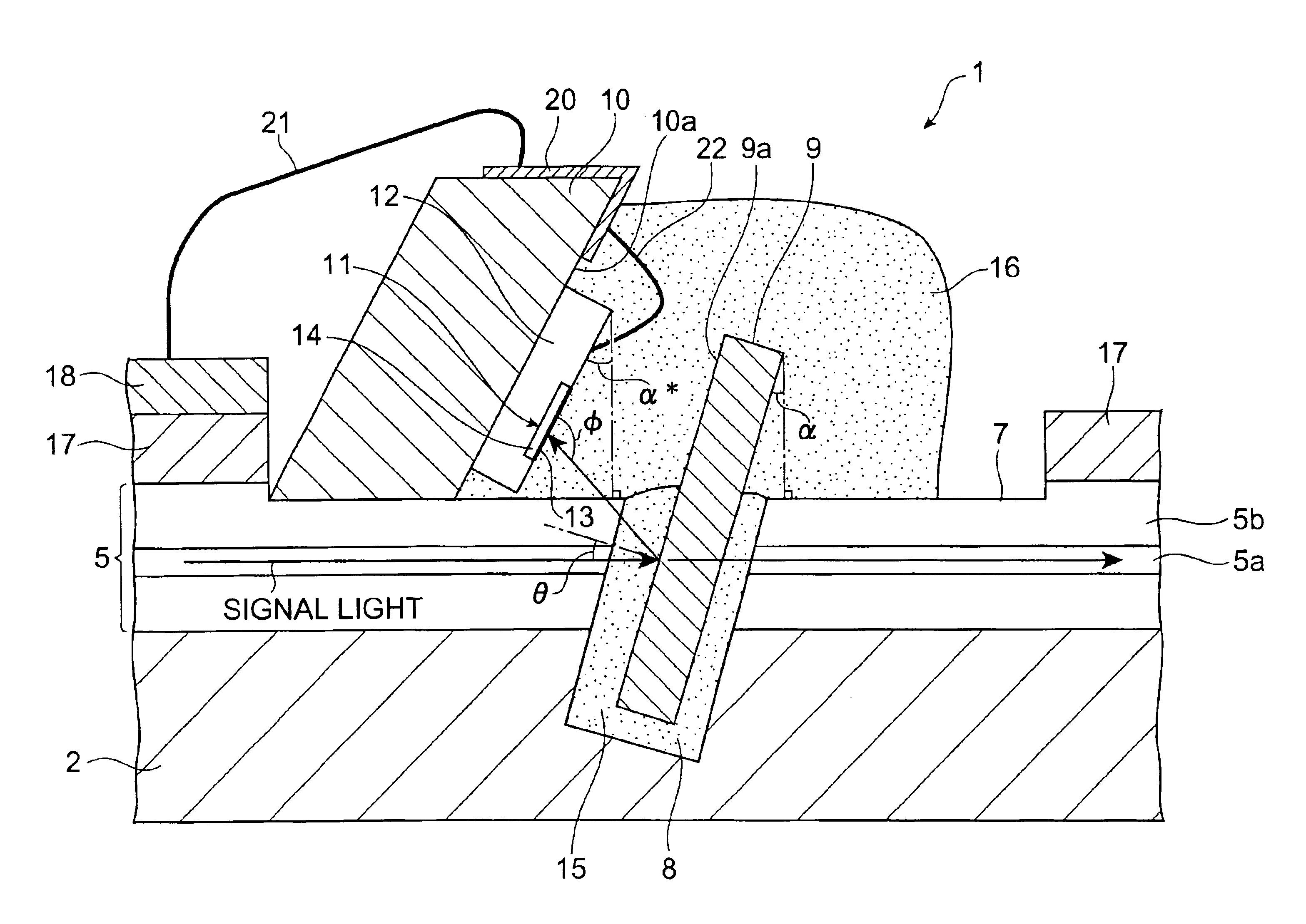
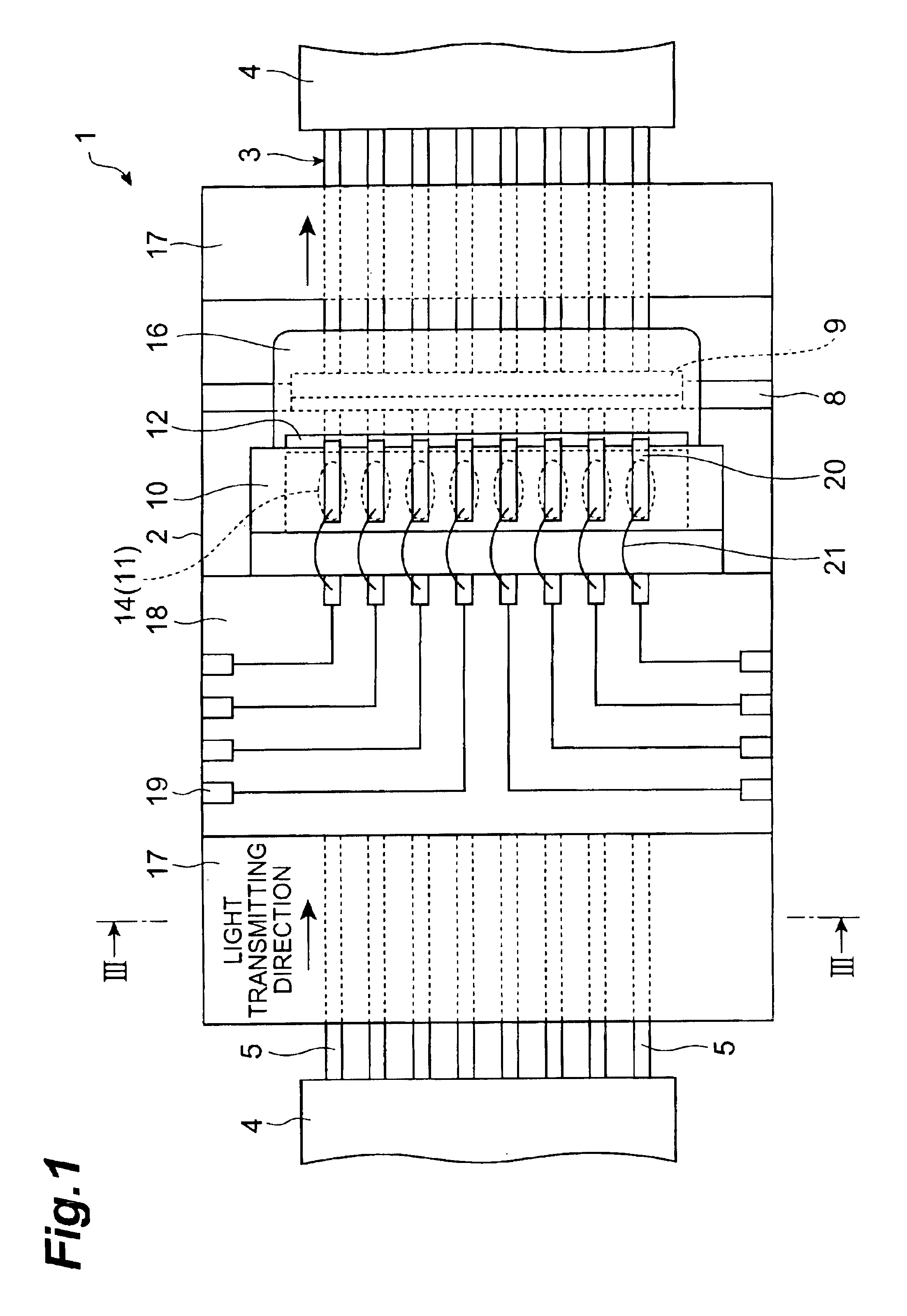
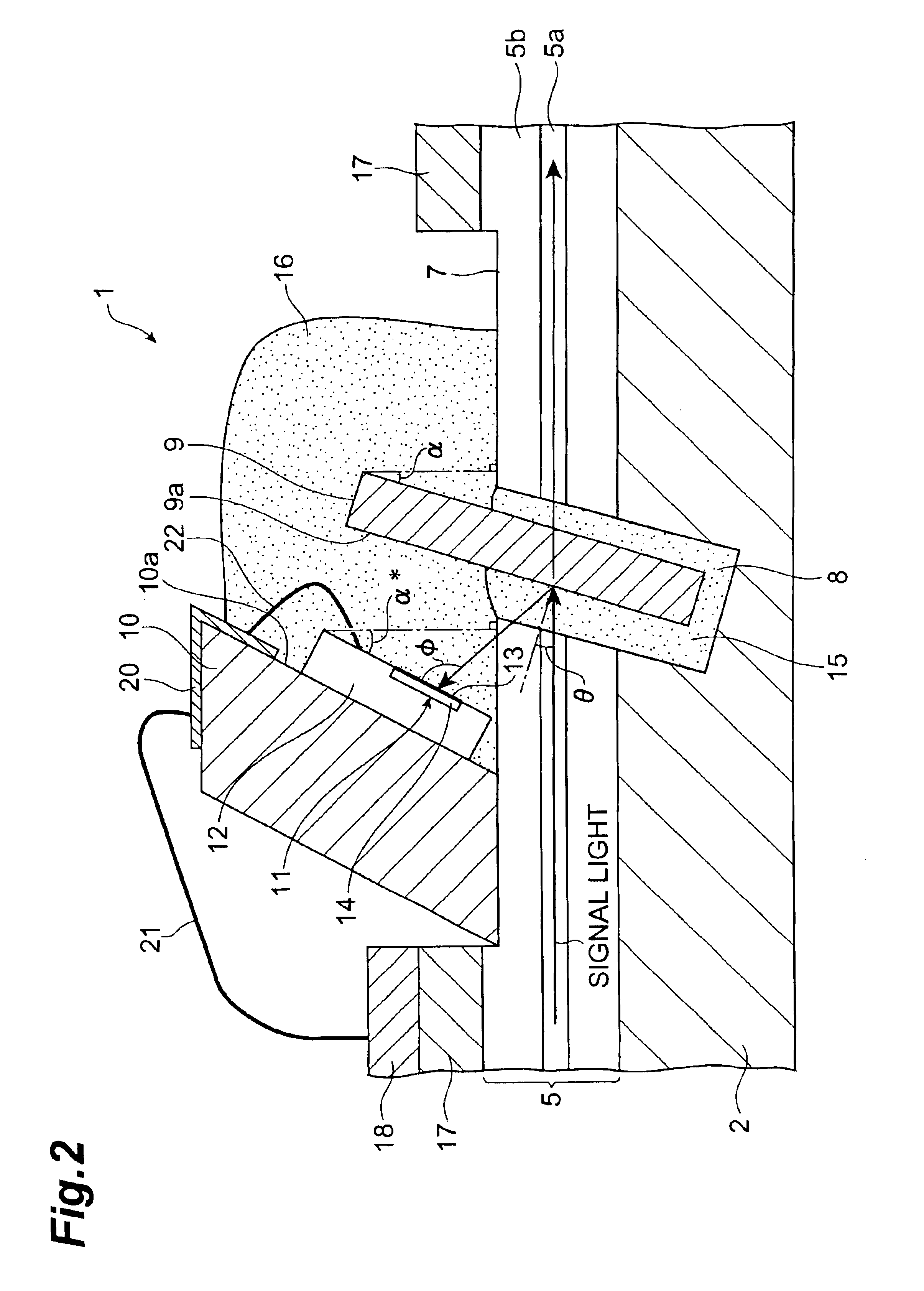
FIG. 1 is a plan view showing the optical device in accordance with the present invention, whereas FIG. 2 is a vertical sectional view showing a part of the optical device. In FIGS. 1 and 2, the optical device 1 in accordance with this embodiment comprises a substrate 2, whereas a plurality of bare fibers 5 exposed from a multicore (eight-core here) coated optical fiber tape 3 by removing a coating 4 from its middle part are secured to an upper face part of the substrate 2. As shown in FIG. 3, the upper face of the substrate 2 is formed with a plurality of fiber-positioning V grooves 6, whereas the bare fibers 5 are secured to the substrate 2 by an adhesive or the like while in a state arranged in their respective V grooves 6.

Each bare fiber 5 is constituted by a core 5a and a cladding 5b disposed thereabout. The bare fiber 5 secured onto the substrate 2 includes a cladding-shaved part 7 formed by shaving the upper side of the cladding 5b toward the central axis of the bare fiber 5....

second embodiment

In FIG. 4, the optical device 30 in accordance with the second embodiment has a lid 17 covering bare fibers 5, whereas the lid 17 is provided with a tilted surface 17a inclined with respect to the upper face of a substrate 2. A support member 31 having a rectangular parallelepiped form is mounted on the tilted surface 17a. A photodetector array 12 having a plurality of photodetectors 11 is attached to one side face (support surface) 31a of the support member 31. As a consequence, the light entrance surface 13 of each photodetector 11 tilts by a desirable angle with respect to the upper face of the substrate 2.

Such an optical device 30 uses the rectangular parallel piped support member 31 having a simple structure, and thus is advantageous in terms of manufacturing. Since such a support member 31 is not disposed on the bare fibers 5 but on the lid 17, the bare fibers 5 are hardly damaged upon attaching the photodetectors 11, whereby the increase of loss in the bare fibers 5 can be re...

third embodiment

In FIG. 5, the optical device 40 in accordance with the third embodiment has a cladding-shaved part 7 formed by shaving the upper part of claddings 5b of bare fibers 5. The cladding-shaved part 7 is formed only on the photodetector 11 side of an optical member 9. On the upper face part of the substrate 2, a lid 17 covering the bare fibers 5 is disposed at the location excluding the cladding-shaved part 7. A transverse groove 8 in which the optical member 9 is inserted is formed so as to extend from the upper face of the lid 17 toward the lower side of the substrate 2. A support member 41 is secured to the lid 17. The support member 41 has a support surface 41a tilted by a desirable angle with respect to the upper face of the substrate 2, whereas a photodetector array 12 having a plurality of photodetectors 11 is attached to the support surface 41a.

Since the length of the cladding-shaved part 7 in the bare fibers 5 is minimized while the support member 41 is not secured onto the bar...


PUM


Abstract

An optical device 1 has a substrate 2, whereas bare fibers 5 exposed from a coated optical fiber tape 3 by removing a coating 4 from its middle part are secured to the upper face part of the substrate 2. In the substrate 2, a transverse groove 8 is formed obliquely with respect to an axis of the bare fibers 5 so as to traverse core parts 5a of the bare fibers. An optical member 9 for reflecting a part of signal light transmitted through the bare fibers 5 is inserted in the transverse groove 8. A support member 10 is provided on the upper side of the bare fibers 5, whereas a support surface 10a of the support member 10 is provided with photodetectors 11 for detecting light reflected by the optical member 9. The support surface 10a of the support member 10 is inclined with respect to the upper face of the substrate 2, whereby the light entrance surface 13 of each photodetector 11 is inclined by a predetermined angle with respect to the upper face of the substrate 2. Such a configuration realizes an optical device which can lower the polarization dependence of received light in the photodetectors.

Description

BACKGROUND OF THE INVENTION1. Field of the InventionThe present invention relates to an optical device for monitoring an optical intensity of an optical signal transmitted through an optical fiber and the like.2. Related Background ArtKnown as an optical device monitoring an optical signal transmitted through an optical fiber is one disclosed in Japanese Patent Application Laid-Open No. HEI 2-15203, for example. The optical fiber type optical demultiplexer disclosed in the above-mentioned publication comprises a substrate whose upper face has an optical fiber secured thereto. The substrate is formed with a groove which is at right angles to the fiber axis of the optical fiber and at an angle of 45° with respect to a side face of the substrate. A wavelength filter is inserted into the groove and bonded thereto. On the substrate, a photodetector is disposed so as to oppose the reflecting surface of the wavelength filter.SUMMARY OF THE INVENTIONIn the above-mentioned prior art, however...

Claims


Application Information

Patent Timeline
Patent Type & Authority Patents(United States)
IPC IPC(8): G02B6/36G02B6/42H01S5/00H01S5/026
CPCG02B6/3636G02B6/4212G02B6/4249G02B6/4246G02B6/4214G02B6/4243G02B6/4251G02B6/4265G02B6/4286G02B6/42
Inventor HARAGUCHI, AKIRAKOMIYA, TAKEOIKEJI, MAKISASAKI, TAKASHIFUJIMURA, YASUSHI
Owner SUMITOMO ELECTRIC IND LTD
Why Eureka
Try Eureka