Collimate lens assembly

a technology of collimate lens and lens body, which is applied in the direction of reflex reflectors, lighting and heating apparatus, instruments, etc., to achieve the effect of improving condensing efficiency

Inactive Publication Date: 2011-04-19
SAMSUNG ELECTRONICS CO LTD
View PDF8 Cites 0 Cited by
  • Summary
  • Abstract
  • Description
  • Claims
  • Application Information

AI Technical Summary

Benefits of technology

[0013]The present invention provides a small-scale collimate lens assembly which has an enhanced condensing efficiency.

Problems solved by technology

Halogen lamps have been widely used as a light source, but these days, metal halide lamps or xenon lamps are being used more frequently than halogen lamps because halogen lamps consume more electric power and heating energy.

Method used


Image

  • Collimate lens assembly
  • Collimate lens assembly
  • Collimate lens assembly

Examples


Embodiment Construction

[0019]Certain exemplary embodiments of the present invention will now be described in greater detail with reference to the accompanying drawings.

[0020]In the following description, the same drawing reference numerals are used for the same elements even in different drawings. The matters defined in the description, such as the detailed construction and elements, are provided to assist in a comprehensive understanding of the invention. Thus, it is apparent that the present invention can be carried out without those specifically defined matters. Also, well-known functions or constructions are not described in detail since they would obscure the invention with unnecessary detail.

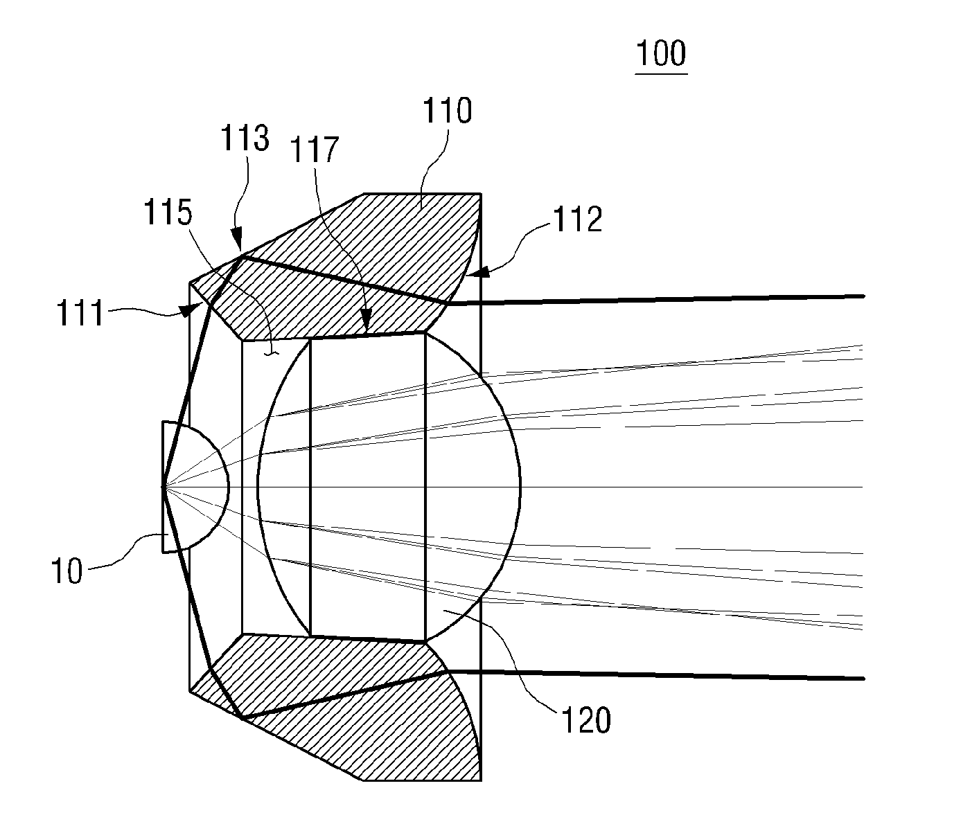
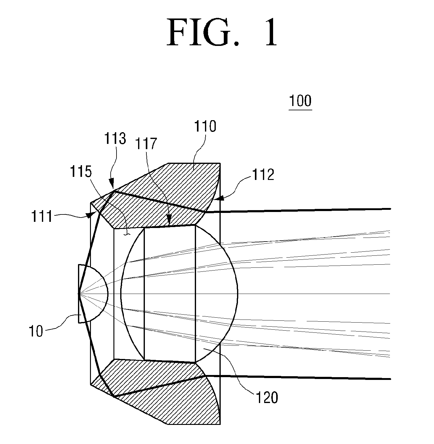
[0021]FIG. 1 is a side sectional view of a collimate lens assembly according to an exemplary embodiment of the present invention, and FIG. 2 is a perspective view of FIG. 1. The reference numeral 10 represents an LED light source.

[0022]The collimate lens assembly 100 of the present exemplary embodiment condenses...


PUM

PropertyMeasurementUnit
sizeaaaaaaaaaa
sizeaaaaaaaaaa
refraction ratioaaaaaaaaaa

Abstract

A collimate lens assembly is provided which includes the first collimate lens which has a total reflection surface and a plurality of refracting surfaces, and the second collimate lens which is connected to the hole, and the second collimate lens has a greater refraction ratio than the first collimate lens.

Description

CROSS-REFERENCE TO RELATED APPLICATIONS[0001]This application claims priority under 35 U.S.C. §119 from Korean Patent Application No. 10-2008-0132575, filed on Dec. 23, 2008, in the Korean Intellectual Property Office, the disclosure of which is incorporated herein by reference in its entirety.BACKGROUND OF THE INVENTION[0002]1. Field of the Invention[0003]Apparatuses and methods consistent with the present invention relate to a light source apparatus of an image display apparatus, and more particularly, to a collimate lens assembly which collimates illumination light of a light source.[0004]2. Description of the Related Art[0005]In general, in an image display apparatus such as a beam projector, a light source apparatus is installed to generate illumination light, and in the light source apparatus, a collimate lens assembly is installed to collimate illumination light irradiated from the light source. The collimate lens assembly bends and reflects the illumination light irradiated ...

Claims


Application Information

Patent Timeline
Patent Type & Authority Patents(United States)
IPC IPC(8): G02B27/30
CPCF21V5/046G02B19/0061G02B19/0028F21Y2101/02F21Y2115/10F21V5/04G02B13/00G02B1/02G02B1/04G02B13/18
Inventor LEE, YOUNG-CHOLHONG, SEOK-CHAN
Owner SAMSUNG ELECTRONICS CO LTD
Why Eureka
Try Eureka