
Microorganism detection apparatus

a technology of microorganisms and detection apparatuses, applied in the direction of optical radiation measurement, luminescent dosimeters, fluorescence/phosphorescence, etc., can solve the problems of increasing the condensing efficiency of the condensing optical system, and affecting the condensing efficiency of the optical system. , to achieve the effect of increasing the condensing efficiency of the optical system

Inactive Publication Date: 2012-06-28
SAMSUNG ELECTRONICS CO LTD +1
View PDF49 Cites 7 Cited by
  • Summary
  • Abstract
  • Description
  • Claims
  • Application Information

AI Technical Summary

Benefits of technology

[0017]Eccentricity of the oval longitudinal section of the mirror chamber may be adjusted and the position of the opening may be adjusted based on the adjusted eccentricity and the numerical aperture of the condensing optical system to increase condensing efficiency of the condensing optical system.
[0033]Eccentricity of the oval longitudinal section of the mirror chamber may be adjusted and the position of the opening may be adjusted based on the adjusted eccentricity to increase condensing efficiency of the condensing optical system.
[0041]Eccentricity of the oval longitudinal section of the mirror chamber may be adjusted and the position of the opening may be adjusted based on the adjusted eccentricity to increase condensing efficiency of the condensing optical system.

Problems solved by technology

Also, contaminants have increased as the result of industrial development, and new varieties of germs and harmful microorganisms have evolved.
In particular, microorganisms, such as bacteria, viruses and mold, in air are known to be a major cause of various fatal diseases including atopic diseases, bronchial diseases and pulmonary diseases.
However, the above method takes several hours to several days to cultivate the collected microorganisms.
Also, some bacteria may not be cultivated using normal methods.
For this reason, diagnosable microorganisms are limited to cultivable microorganisms.

Method used


Image

  • Microorganism detection apparatus
  • Microorganism detection apparatus
  • Microorganism detection apparatus

Examples


Embodiment Construction

[0054]Reference will now be made in detail to the embodiments of the present invention, examples of which are illustrated in the accompanying drawings, wherein like reference numerals refer to like elements throughout.

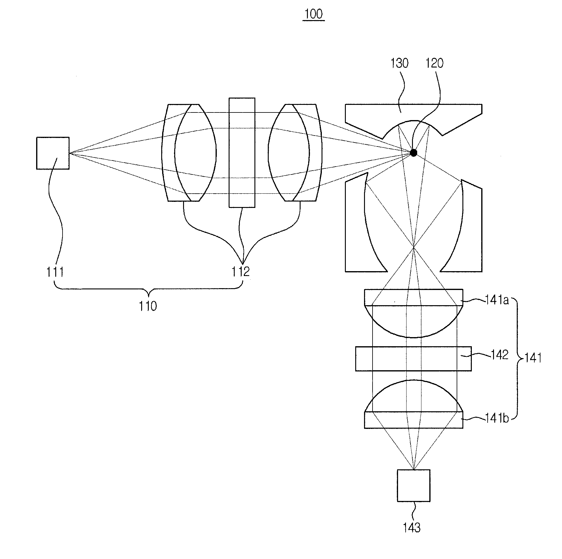
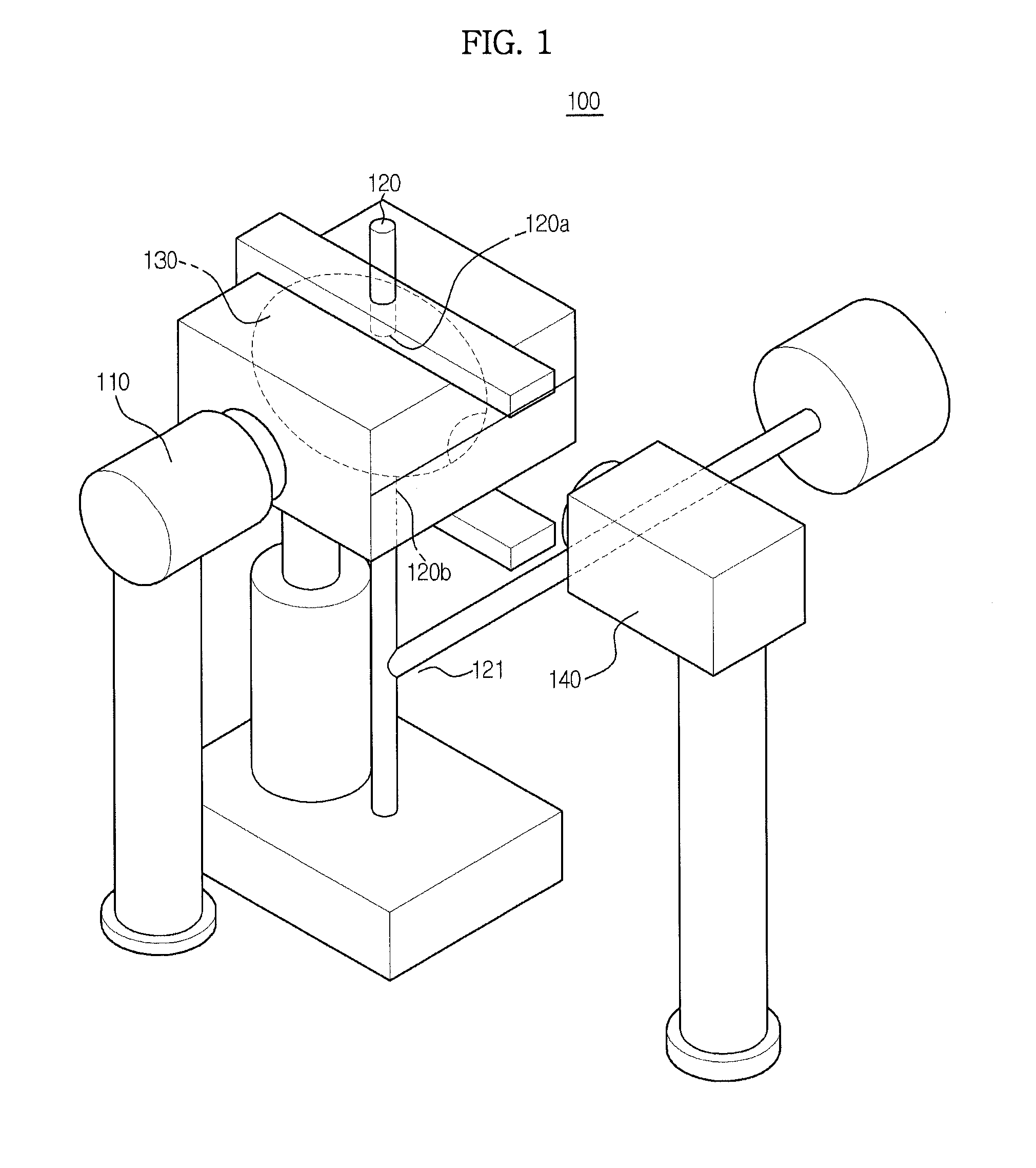
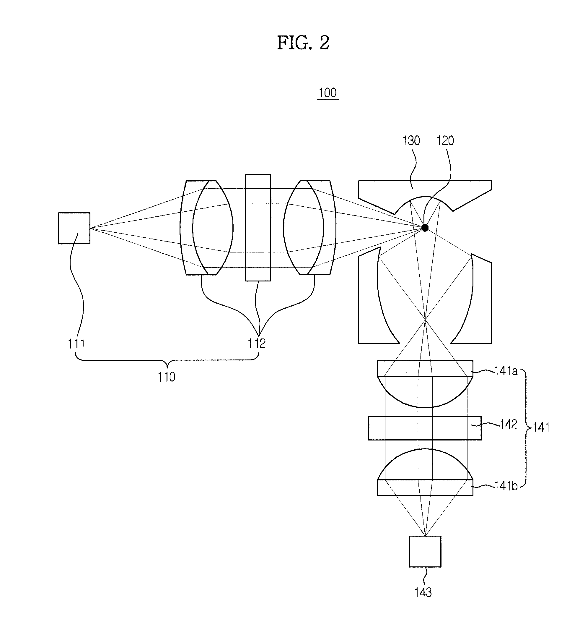
[0055]FIG. 1 shows a microorganism detection apparatus 100 according to an embodiment of the present invention, and FIG. 2 is a sectional view of the microorganism detection apparatus 100 shown in FIG. 1.

[0056]The microorganism detection apparatus 100 includes a light source unit 110, an introduction unit 120, a mirror chamber 130 and a condensing optical system 140.

[0057]The light source unit 110, which irradiates light to particles, includes a light emitting optical element 111 and a converging optical system 112 to converge light emitted from the optical element 111.

[0058]The optical element 111 may include a laser diode (LD) or a light emitting diode (LED).

[0059]In particular, in this embodiment, the optical element 111 emits light of an ultraviolet wavelength band...


PUM

PropertyMeasurementUnit
wavelengthaaaaaaaaaa
reflectanceaaaaaaaaaa
fluorescentaaaaaaaaaa

Abstract

A microorganism detection apparatus including a light source unit to irradiate light, a mirror chamber including a light inlet port and a light outlet port, through which the light is introduced and discharged, respectively an inlet port and an outlet port, through which particles are introduced and discharged, respectively, so that light emitted from the particles (emitted particle light) is generated by the light, and an opening, through which the emitted particle light is discharged outside. The mirror chamber has an oval longitudinal section, and is provided at an inside thereof with a mirror. A condensing optical system is disposed in front of the opening outside the opening to condense the emitted particle light discharged through the opening. Condensing efficiency of the fluorescent light condensing optical system is maximized.

Description

CROSS-REFERENCE TO RELATED APPLICATIONS[0001]This application claims the benefit of Korean Patent Application No. 2010-0133003, filed on Dec. 23, 2010 in the Korean Intellectual Property Office, the disclosure of which is incorporated herein by reference.BACKGROUND[0002]1. Field[0003]Embodiments of the present invention relate to a microorganism detection apparatus to optically detect microorganisms floating in air.[0004]2. Description of the Related Art[0005]In recent years, interest in a clean and safe atmosphere has become increasingly high. Also, contaminants have increased as the result of industrial development, and new varieties of germs and harmful microorganisms have evolved. In particular, microorganisms, such as bacteria, viruses and mold, in air are known to be a major cause of various fatal diseases including atopic diseases, bronchial diseases and pulmonary diseases.[0006]A conventional microorganism detection method includes collecting microorganisms from air, cultiva...

Claims


Application Information

Patent Timeline
Patent Type & Authority Applications(United States)
IPC IPC(8): G01N21/64
CPCG01N2021/6469G01N21/6486
Inventor KWON, JOONHYUNGROH, HEE YUELYOON, DU SEOPKIM, SOO HYUNKWON, WON SIKRYU, SUNG YOONLEE, HYUB
Owner SAMSUNG ELECTRONICS CO LTD
Learn More