
Electricity energy monitor

a technology of energy monitor and monitor, which is applied in the direction of measuring instrument housing, base element modification, instruments, etc., can solve the problems of inability to readily provide a measurement of the consumption of a specific load or group of loads within the premises, inability to measure the total energy consumed at the premises, and bulky prior art devices

Inactive Publication Date: 2011-04-19
VINDEN JONATHAN PHILIP +1
View PDF4 Cites 61 Cited by
  • Summary
  • Abstract
  • Description
  • Claims
  • Application Information

AI Technical Summary

Benefits of technology

"The present invention relates to an electric energy monitor that can measure and record the amount of energy consumed in a household or commercial establishment. The invention is designed to be portable and easy to use, with minimal impact on the existing electrical system. The device can be used in a standard power plug in a standard duplex wall outlet or in a different arrangement, such as a switch or circuit breaker panel. The device is designed to be used continuously in circuit, making it suitable for continuous use. The invention provides a solution for monitoring power consumption in real-time, allowing users to modify their electrical usage behavior and conserve energy."

Problems solved by technology

These methods or devices are only able to measure the total energy consumed at the premises and cannot readily provide a measurement of the consumption of a specific load or group of loads within the premises.
These prior art devices are bulky and expensive, frequently requiring considerable expertise in their implementation and use.
Energy flow through the device is thus accomplished with suitably large current connecting, contacting and conducting means necessitating large, bulky and expensive devices.
The bulkiness of these prior art devices makes their use problematic as the existing arrangements, since power connection to the appliance must be altered.
Additionally, the current contact conducting and measurement means consume considerable energy in their operation.
These prior art devices were not designed to be used continuously in circuit, so these losses are not substantive in the short term.
However, these losses are significant in the long term, rendering such devices unsuitable for continuous use.

Method used


Image

  • Electricity energy monitor
  • Electricity energy monitor
  • Electricity energy monitor

Examples


Embodiment Construction

The present invention can be used continuously without substantially altering the existing arrangements of power connection of ordinary appliances. The invention is simple to use and understand, and operational losses through the use of the invention are minimal.

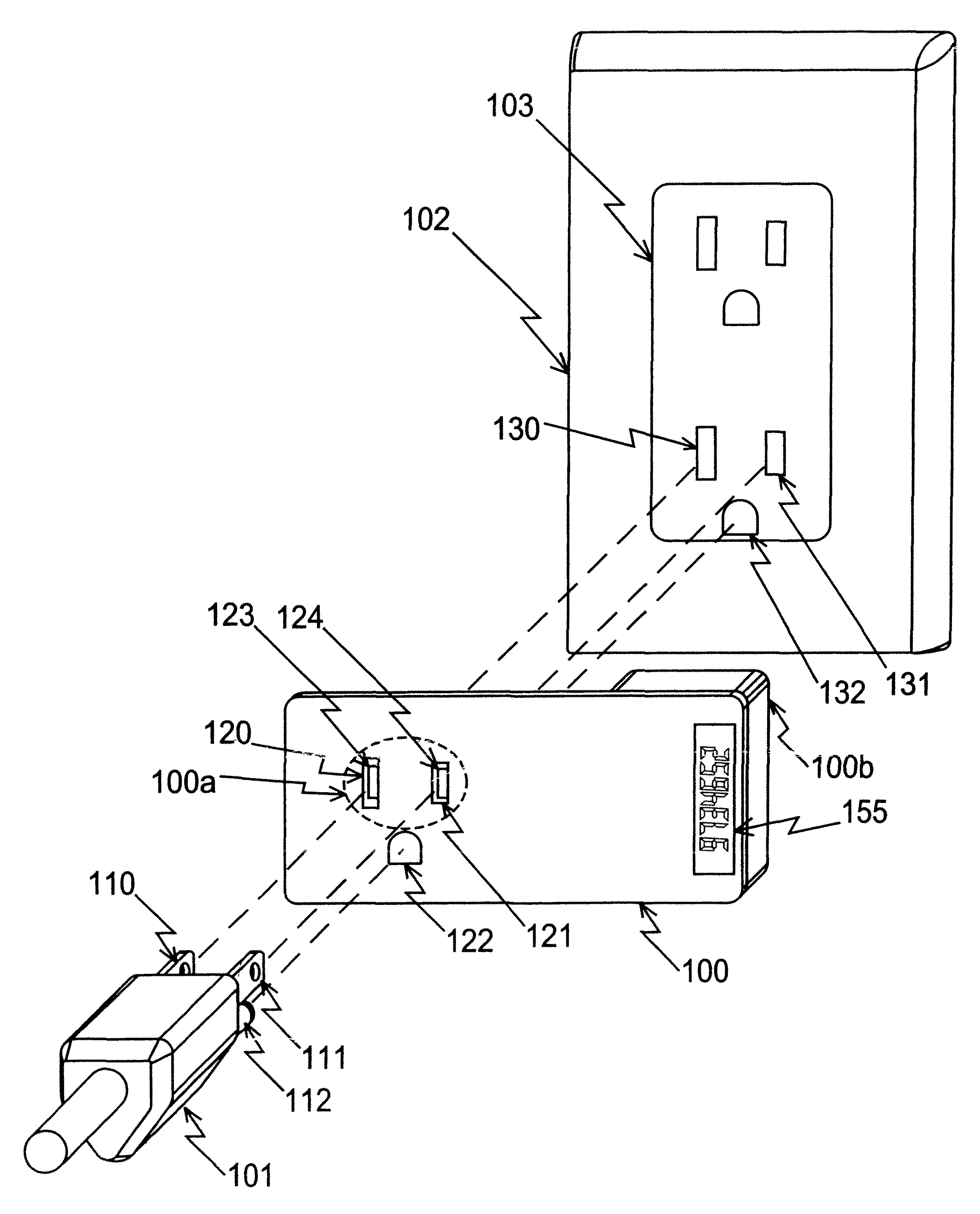
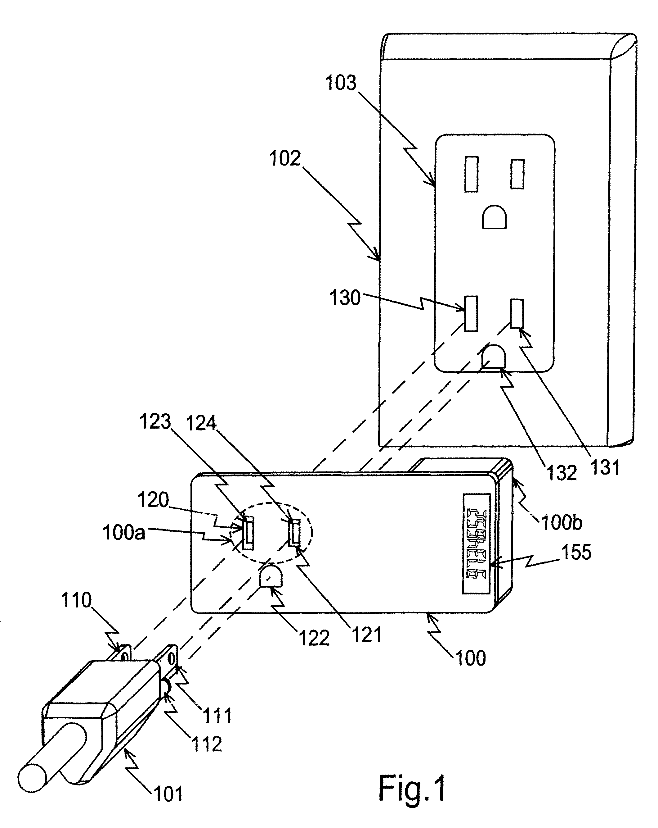
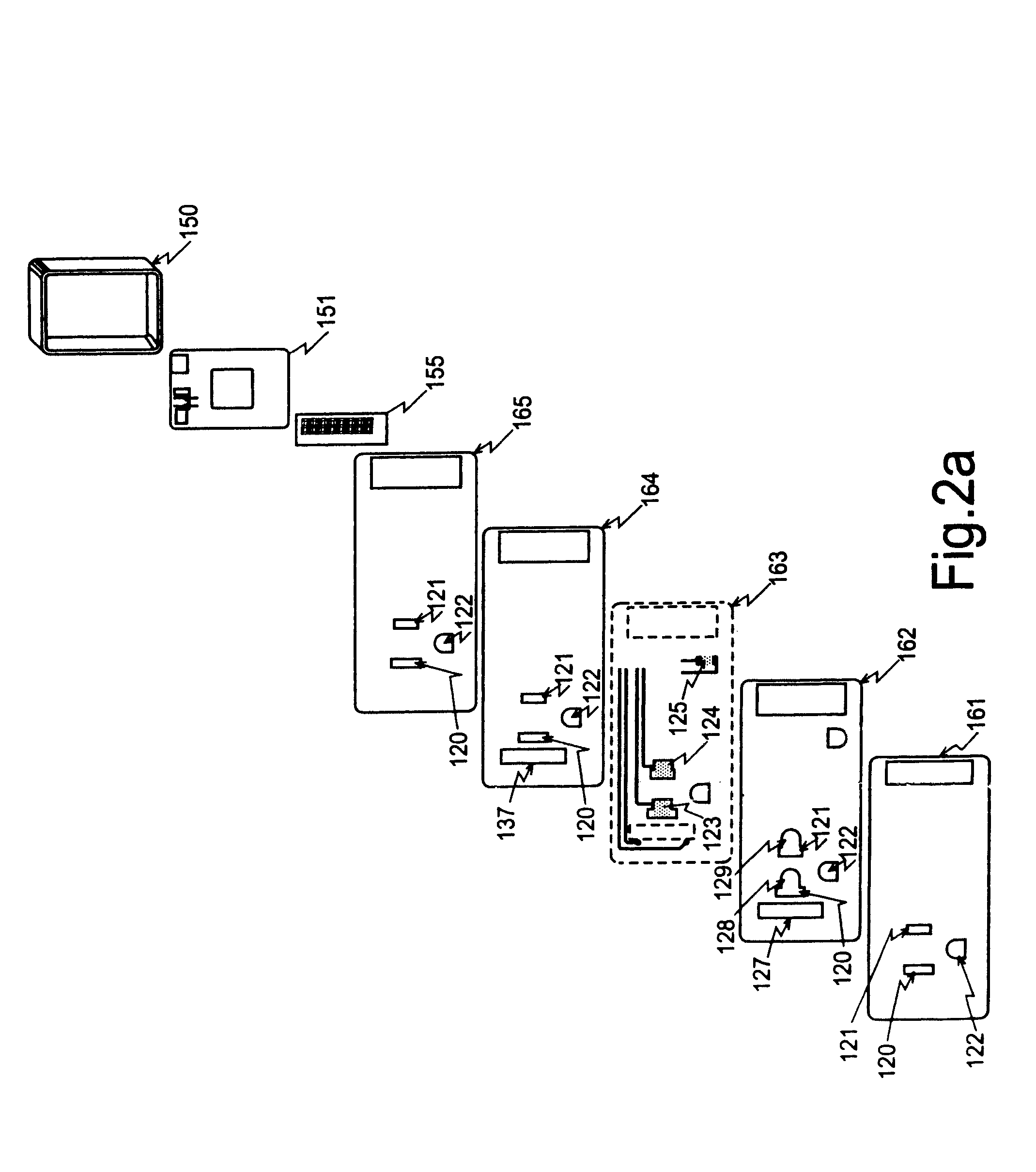
The invention comprises a thin-profile monitoring device through which an electrical conductor, for example the normal line cord plug of an appliance or the output wire from a switch or circuit breaker, is inserted. In the case of a line cord plug which has load conductors comprising blades 110, 111, the line cord plug is then connected to a power receptacle to run the appliance in the normal manner. In the preferred embodiment display on the device shows the accumulated energy (kilowatt hours) which the appliance (or circuit) has used since installation of the monitor.

Parameters of the power consumption such as the present volts, amps, energy rate, peak rate, total energy etc. may be displayed by indexing through a menu wit...


PUM


Abstract

An electric energy monitor or meter for efficient measuring and recording electrical energy usage data relating to a particular appliance or circuit. One embodiment comprises a thin-profile monitoring device through which an electrical conductor, for example the normal line cord plug of an appliance or the output wire from a circuit breaker to the load, is inserted. A display may be provided to show the accumulated energy usage. In other embodiments a device of the invention can be installed in a light switch, appliance, plug, or receptacle. Data can also be transmitted by various means to a computing device such as a personal computer or the like. The device of the invention allows for interaction with Internet-based information dissemination or gathering, meter distribution by means of incentive or promotional give-away, and control of energy usage through connection to an energy management system.

Description

FIELD OF THE INVENTIONThe present invention relates to an electric energy monitor for measuring and recording the electrical energy consumed by a load or a group of loads.BACKGROUND OF THE INVENTIONMeasurement and remote display of the amount of energy consumed in a household or commercial establishment has been possible for a considerable time.Several patents show an implementation that utilizes connection or attachment to the utility electrical power meter. Examples of such patents are: U.S. Pat. No. 4,106,095 to Yarbrough, U.S. Pat. No. 4,207,557 to Gilkeson, U.S. Pat. No. 4,233,590 to Gilkeson and U.S. Pat. No. 4,630,211 to Pettis. Other similar devices that are stand alone energy meters require permanent installation in line or at the distribution box. Examples of such patents are: U.S. Pat. No. 4,080,568 to Funk and U.S. Pat. No. 4,182,983 to Heinrich et al. These methods or devices are only able to measure the total energy consumed at the premises and cannot readily provide a...

Claims


Application Information

Patent Timeline
Patent Type & Authority Patents(United States)
IPC IPC(8): G06F19/00
CPCG01R22/06G01R22/065G01R22/063
Inventor VINDEN, JONATHAN PHILIPGIBSON, JOHN ALAN
Owner VINDEN JONATHAN PHILIP
Learn More