Rotary actuator with internal brake mechanism

a rotary actuator and internal brake technology, applied in the direction of rotary or oscillating piston engines, machines/engines, rotary piston engines, etc., can solve the problems of rotor drift, difficult to prevent leakage across the vane and along the shaft, and reduce the inherent leakage. , the effect of preventing external leakag

Inactive Publication Date: 2011-04-26
WERKHOVEN GARY L
View PDF24 Cites 28 Cited by
  • Summary
  • Abstract
  • Description
  • Claims
  • Application Information

AI Technical Summary

Benefits of technology

[0010]The present invention utilizes continuous seals around the ends of the vane to prevent leakage across the vane and around the pool (shaft) to prevent external leakage. The slow rotational movement of this type of actuator allows for the vane seal to seal against the spool seal. Any inherent leak is thereby minimized.
[0011]The rotary actuator of the present invention further includes a hydraulically-actuated, spring-biased, friction brake mechanism that is operatively deployed between the housing and the spool member for preventing rotation of the spool member relative to the housing whenever hydraulic fluid pressure is being applied to an inlet port below a predetermined pressure value. More particularly, the brake mechanism includes a spring-biased piston that is adapted to cooperate with mating surfaces on the spool member to releasably lock the spool member to the housing and wherein the piston overcomes a force of at least one spring to release the lock when a predetermined hydraulic pressure is present in a space between one end surface of the stop member and the vane.

Problems solved by technology

Also known in the art is the need for effective seals for preventing leakage of the high pressure hydraulic fluid past the vane which seriously detracts the efficiency of the hydraulic actuator and results in rotor drift.
It is very difficult to prevent leakage across the vane and along the shaft (out of the actuator unit).
Should the hydraulic brake line fail, the load would be free to swing which, of course, is highly undesirable and unsafe.

Method used


Image

  • Rotary actuator with internal brake mechanism
  • Rotary actuator with internal brake mechanism
  • Rotary actuator with internal brake mechanism

Examples


Embodiment Construction

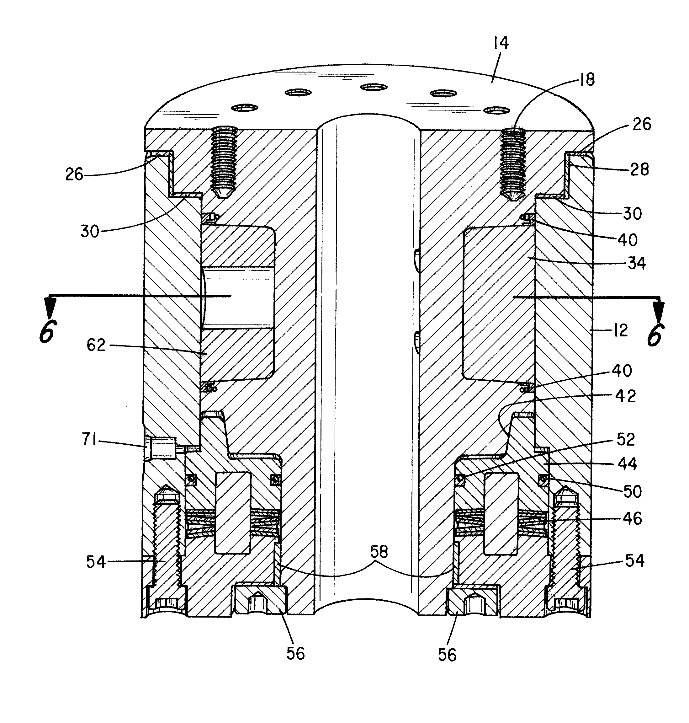
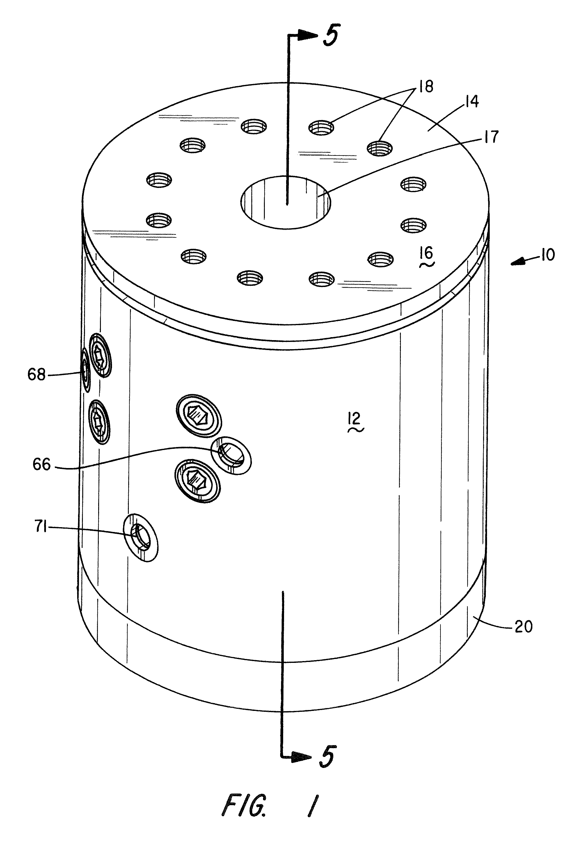
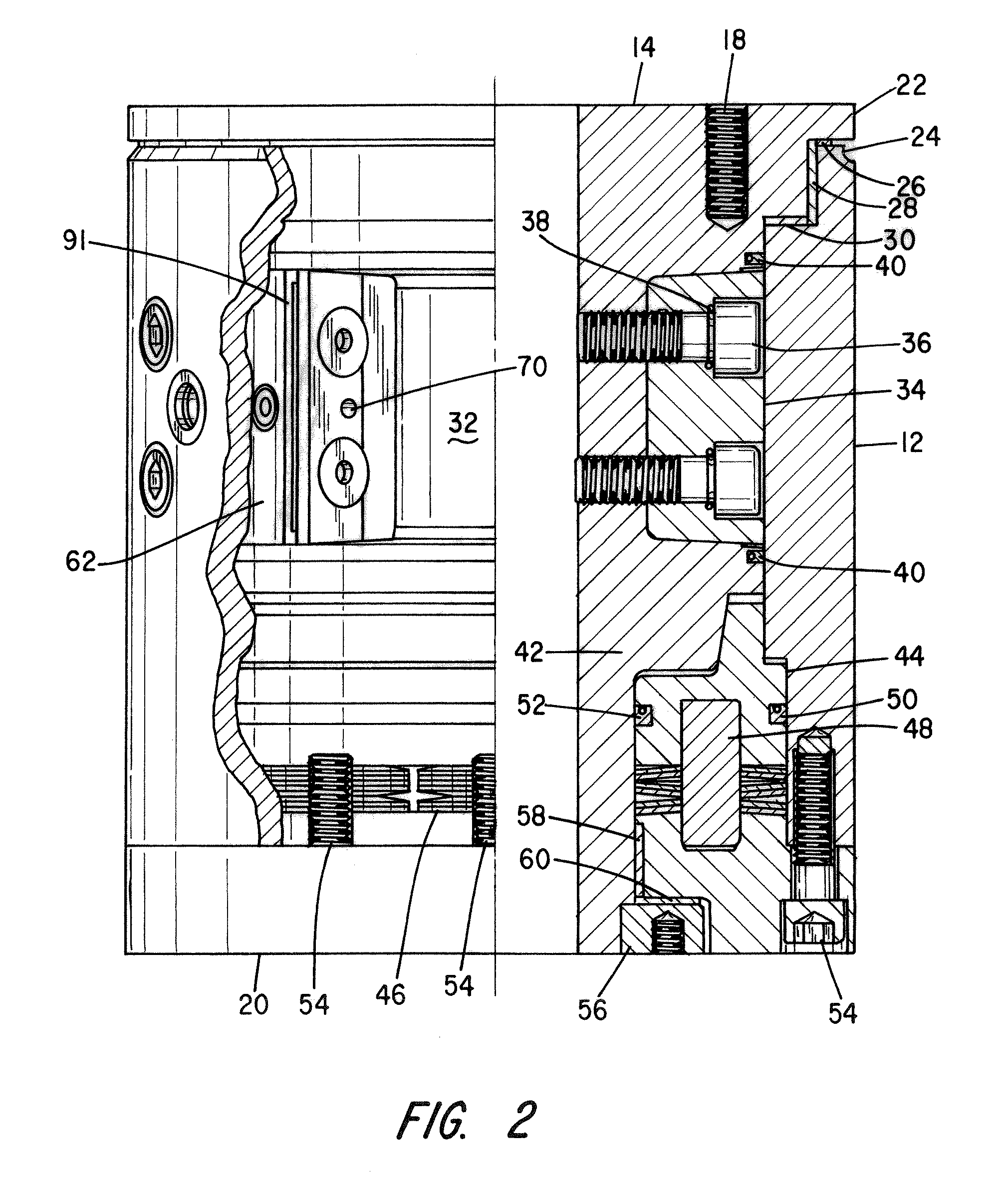
[0019]Referring first to FIG. 1, there is shown a perspective view of the rotary actuator assembly comprising a preferred embodiment of the present invention. It is indicated generally by numeral 10 and is seen to comprise a generally cylindrical housing 12 in which is journaled a spool member 14. That is to say, the spool member 14 is rotationally mounted within the housing 12, and visible on the upper surface 16 of the spool member is a central bore 17 and a plurality of threaded bores 18 arranged in a circular pattern by which the actuator assembly can be attached to one of a frame or load. The central bore 17 reduces the weight of the structure when foot mounted and also allows straddle mounting by inserting a support shaft through this bore. In the case of straddle mounting, the housing 12 is equipped with mounting feet (not shown) to secure it to a stationary member.

[0020]Bolted to the lower edge of the housing 12 is a cap member 20 and it, too, includes a pattern of threaded ...


PUM


Abstract

A vane type hydraulic rotary actuator incorporates a fail-safe brake for preventing movement of the device's rotor relative to a housing in which the rotor is journaled. The brake has a spring-biased piston that is forced to a locked condition whenever applied hydraulic operating pressure acting on the vane falls below a predefined limit. The rotary actuator also incorporates an improved sealing arrangement that prevents egress of hydraulic fluid from a high pressure chamber on one side of the vane to a low pressure chamber on the opposite side of the vane.

Description

BACKGROUND OF THE INVENTION[0001]I. Field of the Invention[0002]The present invention relates generally to a hydraulic rotary actuator of the vane type, and more particularly to such a rotary actuator having improved seal structures and a fail-safe brake mechanism.[0003]II. Discussion of the Prior Art[0004]Hydraulic rotary actuators find application in a number of fields where it is desired to rotate a load through a predetermined angle relative to a stationary frame member. For example, a few applications use rotary actuators for controlling the positioning of a bucket on the end of a boom on a power company's utility truck, the rotation of the bucket on a backhoe and tipping refuse containers on refuse collection vehicles.[0005]A typical vane-type hydraulic rotary actuator comprises a stator housing with a rotor journaled for rotation within the housing that defines an annular chamber between the rotor surface and the stator. Affixed to the rotor and cooperating with a cylindrical...

Claims


Application Information

Patent Timeline
Patent Type & Authority Patents(United States)
IPC IPC(8): F01C9/00F15B15/26
CPCF15B15/262F15B1/12F15B15/12
Inventor WERKHOVEN, GARY L.
Owner WERKHOVEN GARY L
Why Eureka
Try Eureka