Eureka AIR delivers breakthrough ideas for toughest innovation challenges, trusted by R&D personnel around the world.

Beam combining device and projector having such beam combining device

a beam combining and beam technology, applied in the direction of projectors, instruments, optics, etc., can solve the problems of unidirectional brightness of color beams to be projected, white is often suffering from chromatic aberration, and the configuration of the projector of figs. 2a and 2b still has some drawbacks, so as to achieve enhanced brightness values and the effect of reducing the overall volume of the projector and enhancing the uniformity of color beams

Inactive Publication Date: 2011-04-26
YOUNG OPTICS
View PDF5 Cites 6 Cited by
  • Summary
  • Abstract
  • Description
  • Claims
  • Application Information

AI Technical Summary

Benefits of technology

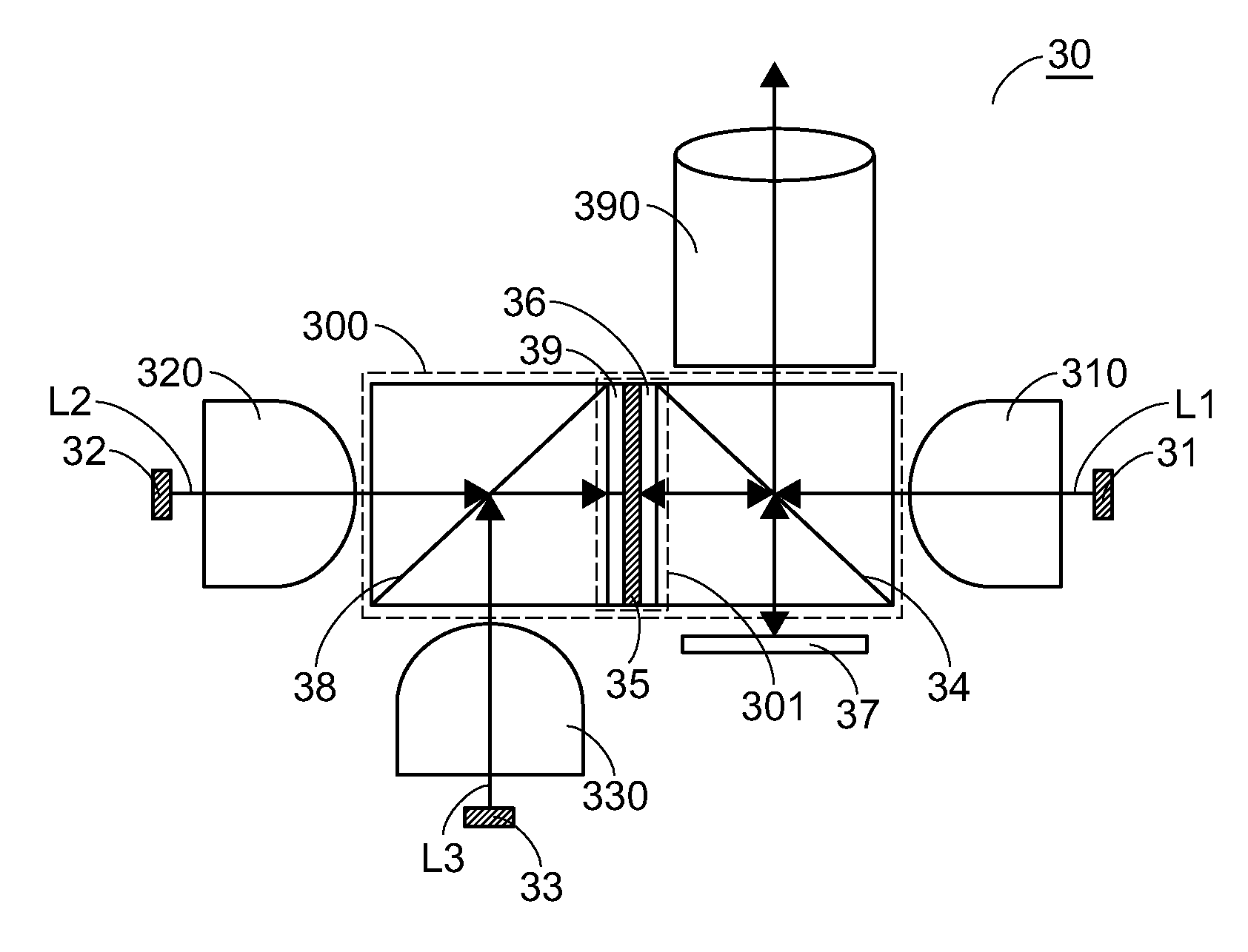
[0016]The beam combining device and the projector in accordance with the embodiment of the present invention are capable of homogenizing the color beams that are emitted by the color light sources, so that the overall volume of the projector is reduced. Since the optical path lengths of the three primary color beams (i.e. the red, green and blue beams) are equal, the brightness values and the uniformity of the color beams to be projected are enhanced and the chromatic aberration is overcome. By using the beam combining device and the projector of the present invention, the image mixed by the three primary color beams has uniform brightness values.

Problems solved by technology

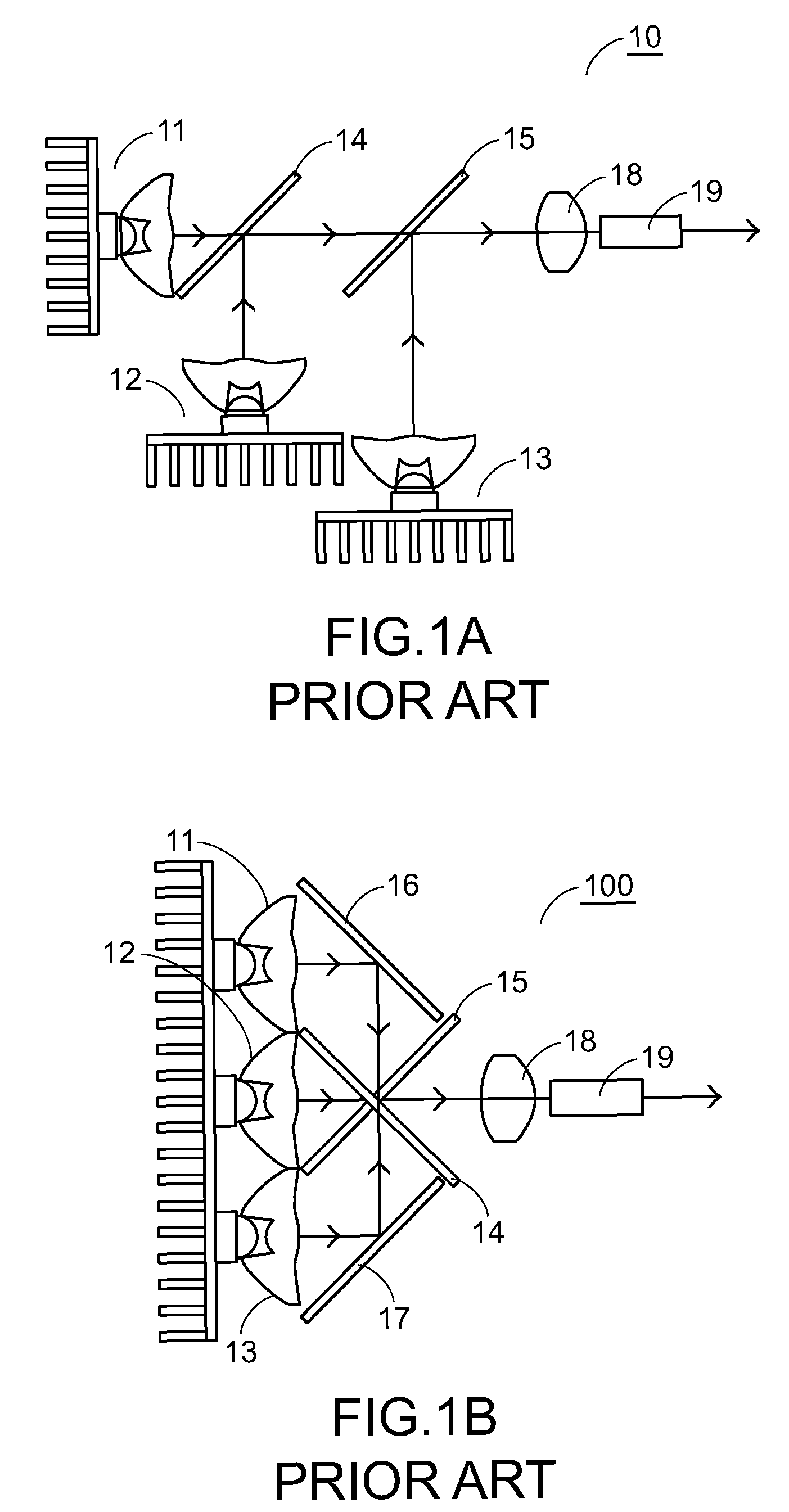
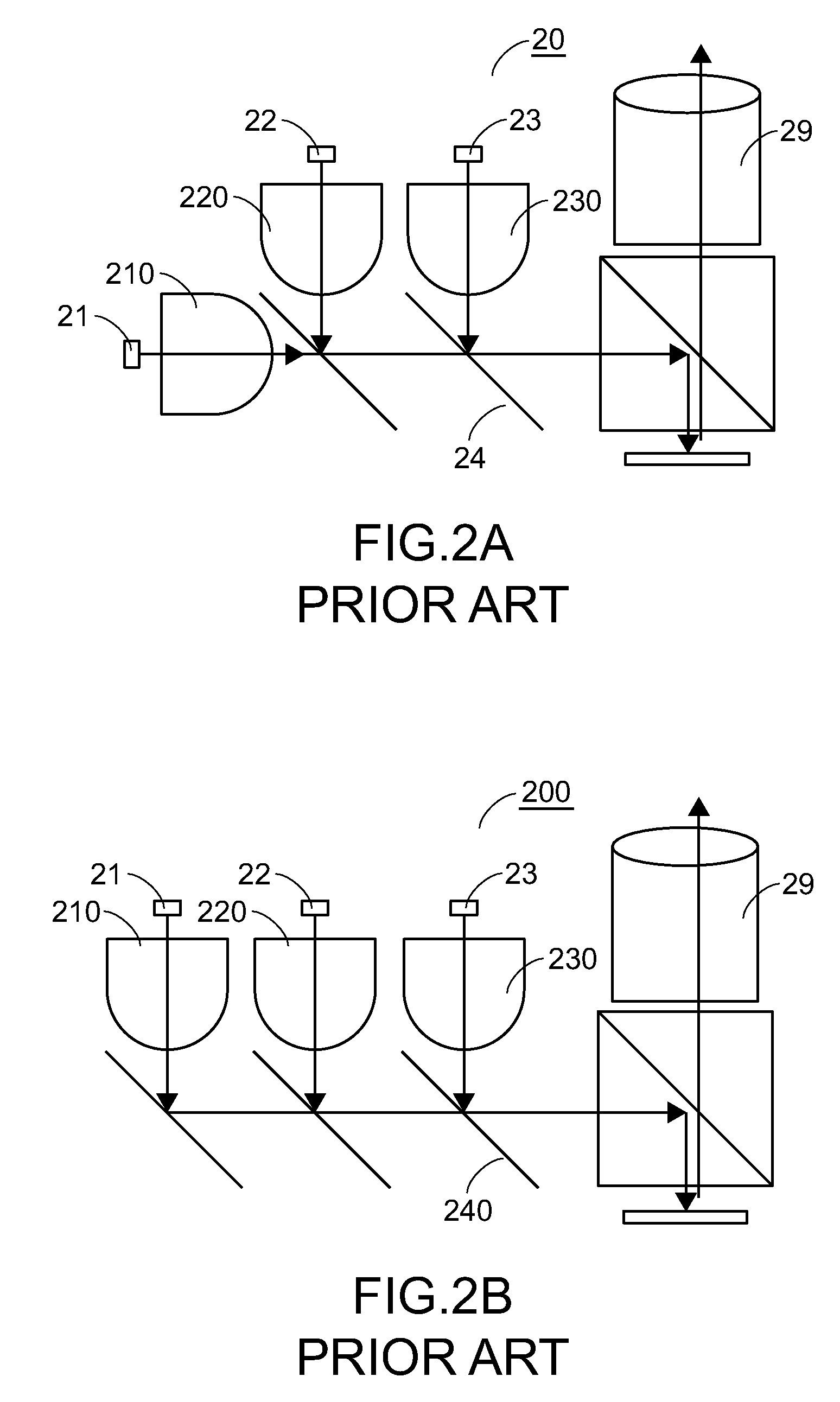
The internal configurations of the projectors of FIGS. 2A and 2B, however, still have some drawbacks.
In a case that optical path lengths are not completely equal, the brightness values of the color beams to be projected are not uniformly distributed.
For example, when three primary colors (i.e. the red, green and blue beams) are mixed to produce a white beam, the resulting white is often suffered from chromatic aberration due to the non-uniform brightness values.
In some circumstances, the colors of resulting image are shown as non-uniformly distributed loops and the color uniformity is deteriorated.

Method used


Image

  • Beam combining device and projector having such beam combining device
  • Beam combining device and projector having such beam combining device
  • Beam combining device and projector having such beam combining device

Examples


Embodiment Construction

[0027]In the following detailed description of the preferred embodiments, reference is made to the accompanying drawings which form a part hereof, and in which are shown by way of illustration specific embodiments in which the invention may be practiced. In this regard, directional terminology, such as “top,”“bottom,”“front,”“back,” etc., is used with reference to the orientation of the Figure(s) being described. The components of the present invention can be located in a number of different orientations. As such, the directional terminology is used for purposes of illustration and is in no way limiting. On the other hand, the drawings are only schematic and the sizes of components may be exaggerated for clarity. It is to be understood that other embodiments may be utilized and structural changes may be made without departing from the scope of the present invention. Also, it is to be understood that the phraseology and terminology used herein are for the purpose of description and s...


PUM


Abstract

A beam combining device and a projector having such a beam combining device are provided. The projector includes a first color light source, a second color light source, a third color light source, a beam combining device, a light valve and a projection unit. The first color light source, the second color light source and the third color light source respectively emit first, second and third color beams. The beam combining device includes a polarization state converting module, a color separation unit and a polarization beam splitter. The optical path lengths of the first color beam emitted from the first color light source to the polarization beam splitter, the second color beam emitted from the second color light source to the polarization beam splitter, and the third color beam emitted from the third color light source to the polarization beam splitter are equal.

Description

FIELD OF THE INVENTION[0001]The present invention relates to a beam combining device and a projector having such a beam combining device, and more particularly to a beam combining device for mixing three primary color beams that are emitted by three primary color light sources of a projector, in which the optical path lengths of the color beams propagated in the beam combining device are equal.BACKGROUND OF THE INVENTION[0002]With rapid development of digitalized techniques, projectors become essential electronic appliances in many applications. For example, projectors may be used for making presentations, holding meetings or giving lectures in classrooms, boardrooms or conference rooms. Recently, projectors may be used for viewing movies in home theaters or projecting images in home-use TV game consoles. For enhancing operating performance and fulfilling visual enjoyment, most projectors have large-sized screen for projecting images thereon.[0003]Generally, projectors are operated ...

Claims


Application Information

Patent Timeline
Patent Type & Authority Patents(United States)
IPC IPC(8): G02B27/18G02B27/28
CPCG02B27/283
Inventor CHEN, SUNG-NANCHEN, CHAO-SHUN
Owner YOUNG OPTICS
Why Eureka
Eureka Blog
Learn More