
Sensor and guide wire assembly

a technology of guide wires and sensors, applied in the direction of guide wires, sensors, medical science, etc., can solve the problem of leaving a very limited space for the sensitive signal transmitting conductors, and achieve the effect of reducing the diameter

Inactive Publication Date: 2011-04-26
ST JUDE MEDICAL COORDINATION CENT
View PDF14 Cites 36 Cited by
  • Summary
  • Abstract
  • Description
  • Claims
  • Application Information

AI Technical Summary

Benefits of technology

The present invention provides a new and improved design for a sensor and guide wire assembly that exhibits better mechanical performance when maneuvered in small and tortuous vessels. The assembly includes a hollow stranded wire that determines the overall mechanical properties of the sensor guide, and the stiffness and other characteristics of the guide wire can be varied by modifying the wire in different ways. The technical effects of the invention include improved maneuverability and better mechanical performance of the sensor and guide wire assembly.

Problems solved by technology

Thus, to provide the necessary stiffness and pushability, the solid metal wire must occupy a large portion of the available space inside the flexible tube, thereby leaving a very limited space for the sensitive signal transmitting conductors.

Method used


Image

  • Sensor and guide wire assembly
  • Sensor and guide wire assembly
  • Sensor and guide wire assembly

Examples


first embodiment

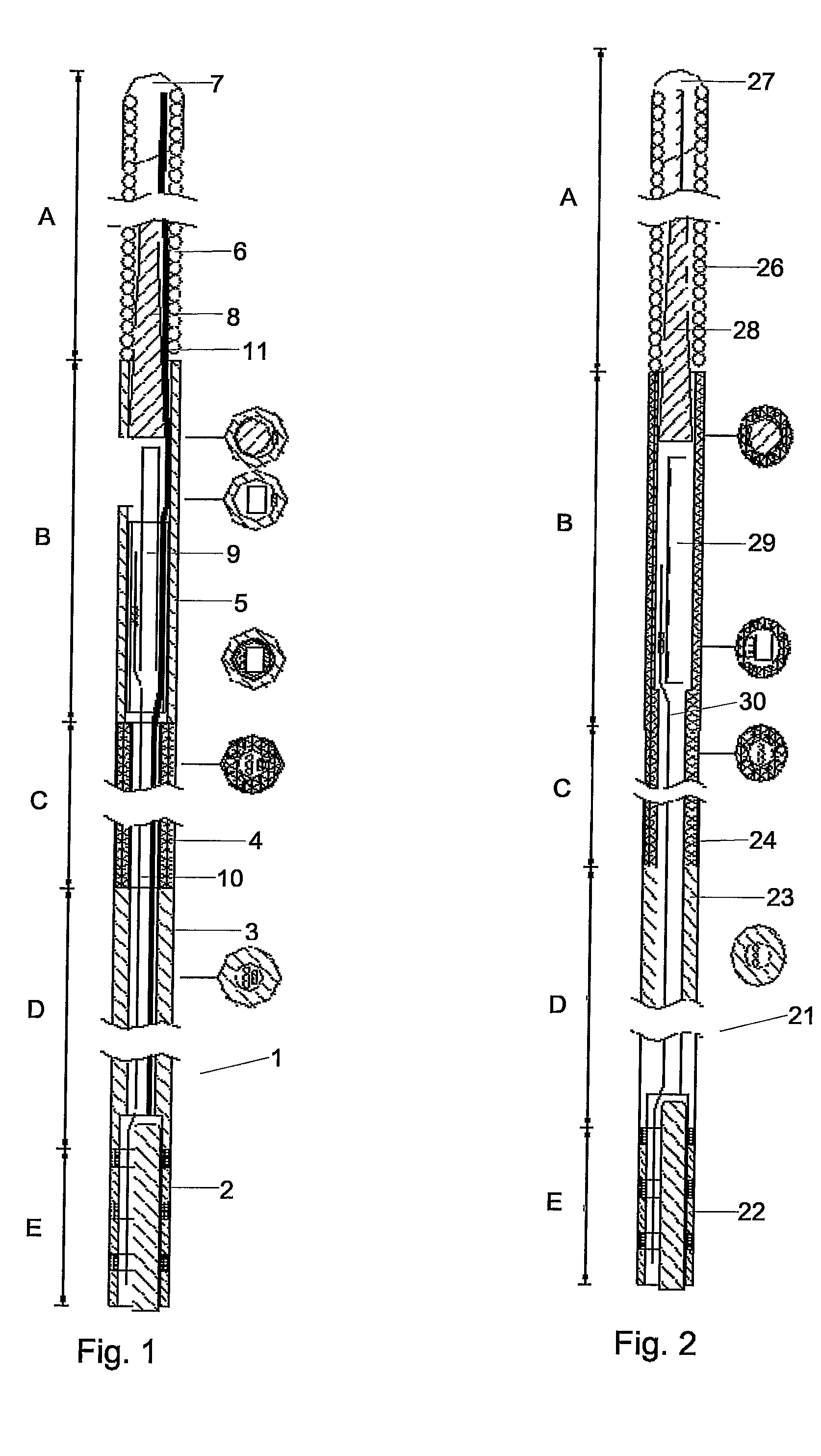
[0020]FIG. 1 illustrates schematically a sensor and guide wire assembly 1 according to the present invention. The sensor assembly 1 comprises a proximal portion 2 comprising a male connector, a flexible proximal tube 3, a hollow stranded wire 4, a jacket or sleeve 5, a coil 6 having a tip 7, a distal core wire 8, and a sensor element 9, which is connected to the male connector by at least one electrical lead 10. In use, the male connector in the proximal portion 2 is inserted into a corresponding female connector (not shown in the figure), such that measurement signals from the sensor element 9 can be displayed as curves or numbers on a suitable display unit (not shown in the figure). The sensor assembly 1 comprises further a so-called safety wire 11, which is attached in the tip 7 and extends preferably to the proximal connector 2. In case of an accidental break of the sensor assembly 1 when, for example, a doctor tries to push the sensor assembly 1 through a sharp bend in an arter...

second embodiment

[0030]a sensor and guide wire assembly 21 is illustrated in FIG. 2. The sensor assembly 21 comprises a proximal portion 22 comprising a male connector, a flexible proximal tube 23, a hollow stranded wire 24, a coil 26 having a tip 27, a distal core wire 28, and a sensor element 29, which is connected to the male connector in the proximal portion 22 by least one electrical lead 30. The sensor assembly 21 of FIG. 2 differs from the sensor assembly 1 of FIG. 1 in that there is no jacket or sleeve provided. The sensor element 29 is instead arranged within the hollow stranded wire 24. To improve the communication between the sensor element 29 and the ambient medium, e.g. blood, one or several strands could be removed from a portion of the hollow stranded wire 24. In the embodiment shown in FIG. 2, there is no safety wire provided, but it should be understood that such a safety wire could be provided also for this embodiment. It should further be noted that a portion of the hollow strande...


PUM


Abstract

Sensor and guide wire assembly (1; 21) for intravascular measurement of physical variables inside a living body and comprises a proximal end portion (2; 22) and a sensor element (9; 29), which is located in a distal portion of the sensor and guide wire assembly (1; 21), and is characterized in that a proximal tube (3; 23) is provided, which extends from said proximal portion (2; 22) to a proximal end of a hollow stranded wire (4; 24), which extends to the distal end portion wherein the sensor element (9; 29) is located.

Description

FIELD OF THE INVENTION[0001]The present invention relates generally to sensor and guide wire assemblies, in which a sensor element is mounted at the distal end of a guide wire for intravascular measurements of physiological variables in a living body, and in particular to the design and construction of the guide wire. The present invention also relates to a hollow stranded wire for a sensor and guide wire assembly as well as a method of modifying the mechanical properties of the hollow stranded wire.BACKGROUND OF THE INVENTION[0002]Sensor and guide wire assemblies in which a sensor is mounted at the distal end of a guide wire are known. In U.S. patent Re. 35,648, which is assigned to the present assignee, an example of such a sensor and guide wire assembly is disclosed, where a sensor guide comprises a sensor element, an electronic unit, a signal transmitting cable connecting the sensor element to the electronic unit, a flexible tube having the cable and the sensor element disposed ...

Claims


Application Information

Patent Timeline
Patent Type & Authority Patents(United States)
IPC IPC(8): A61B5/00A61M25/00A61B5/0215A61M25/09
CPCA61B5/00A61B5/0215A61M25/09A61B5/6851A61M2025/09191A61M2025/09083
Inventor VON MALMBORG, PARDURING, ERIKKARLSSON, STAFFAN
Owner ST JUDE MEDICAL COORDINATION CENT
Learn More