Water separator for a steam turbine plant

a technology for steam turbine plants and water separators, which is applied in steam engine plants, machines/engines, chemical/physical processes, etc., can solve the problems of significant part of the overall cost of the water separator, the construction of pipes necessary for the discharge of steam, and avoid the consumption of labor and costs associated with it. , the effect of simplifying and cost-effectiveness

Active Publication Date: 2011-04-26
GENERAL ELECTRIC TECH GMBH
View PDF13 Cites 11 Cited by
  • Summary
  • Abstract
  • Description
  • Claims
  • Application Information

AI Technical Summary

Benefits of technology

[0011]One of numerous aspects of the present invention includes a preseparator or water preseparator for steam turbine plants which can maintain the (high) velocity of the steam from the exhaust steam housing of a high-pressure steam turbine, which separator in comparison to the separators of the prior art requires a smaller pipe construction and can be installed at lower costs and with lower operating expenditure, especially in the case of retrofits of existing plants.
[0014]In the water preseparator in this embodiment, as in the separators of the prior art, a water film is formed on the wall of the feed pipe. This water flows down through the gap between feed pipe and the inflow section of the steam transfer pipe, wherein this water flow is assisted by a transporting steam flow for the purpose of avoiding a build-up of water at the gap. The transporting steam flows through the gap and then along the built-in fittings outside the steam transfer pipe, first of all in the flow direction of the operating steam. The transporting steam then flows with a sharp change of direction around the end of the built-in fittings, wherein water in the transporting flow drops downwards on account of its inertia and is separated from the transporting steam. After the deflection, the transporting steam reaches the start of the steam transfer pipe and, after a further deflection, enters the steam transfer pipe there through the gap between inflow section and steam transfer pipe. The constriction of the inflow section of the steam transfer pipe achieves the effect of a Venturi-nozzle by an underpressure being formed in the inflow section in the steam transfer pipe, which forces the flow of transporting steam around the baffle into the steam transfer pipe. As a result, a recycling of the transporting steam, which is diverted from the operating steam in the feed pipe, is achieved back into the operating steam in the steam transfer pipe.
[0017]By implementation of embodiments according to the invention, the requirement of a transporting steam pipe from the separator housing into a further part of the steam turbine plant, as was necessary in plants of the prior art, can be dispensed with. The consumption of labor and costs which is associated with it is therefore avoided. Since in the case of preseparators of the prior art, the construction of such pipes typically constitutes a significant part of the construction costs of the entire separator, this measure signifies an appreciable cost reduction. The construction and especially a retrofit of a preseparator according to the invention can consequently be realized in a greatly simplified and more cost-effective manner.

Problems solved by technology

In both of these separators, the costs of the pipe construction which is necessary for the discharge of transporting steam amount to a significant part of the overall costs of the water separator.

Method used


Image

  • Water separator for a steam turbine plant
  • Water separator for a steam turbine plant
  • Water separator for a steam turbine plant

Examples


first embodiment

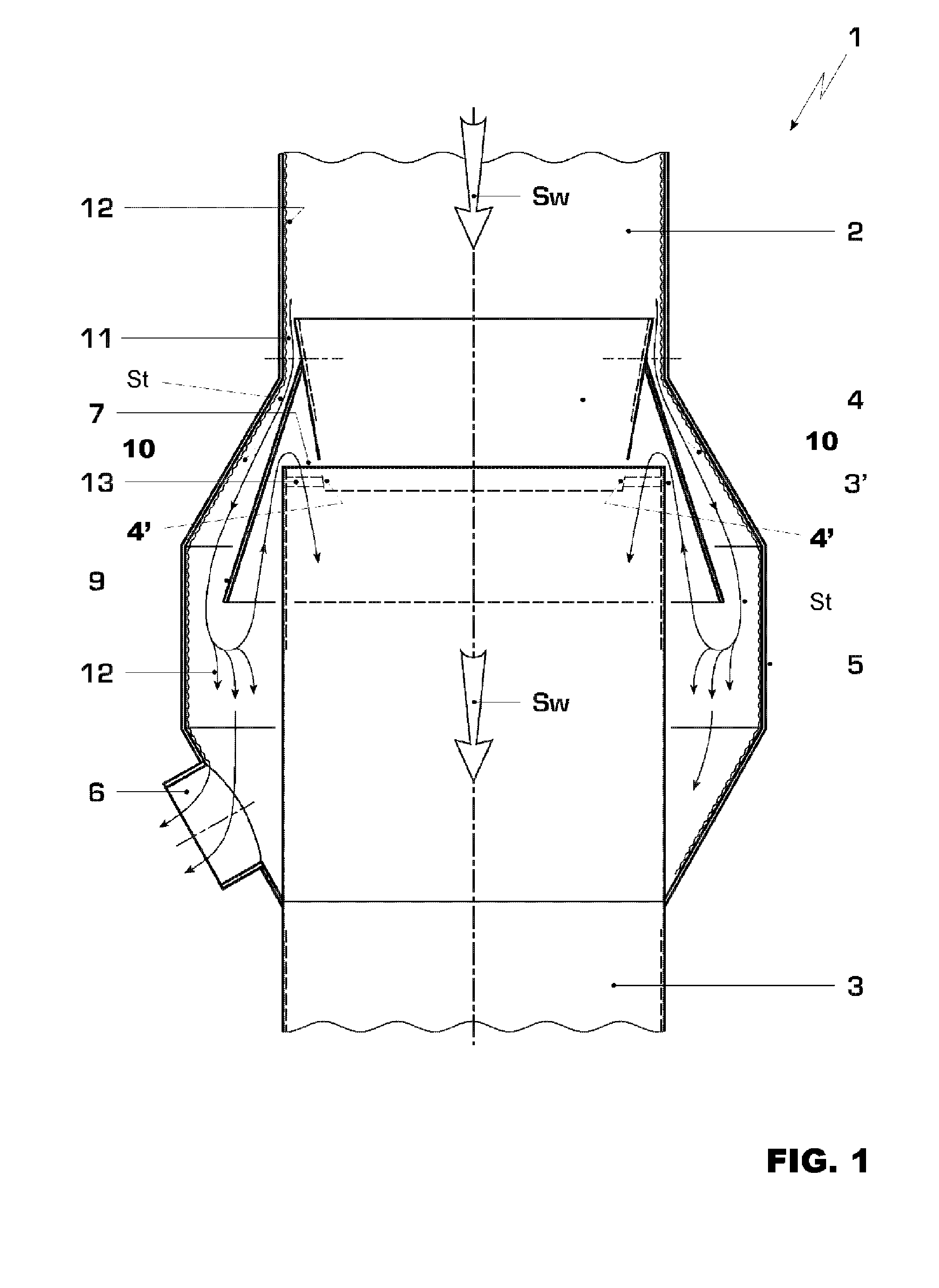
[0021]FIG. 1 shows an example of a preseparator 1 according to the A feed pipe 2 is shown, through which the steam from the exhaust steam housing of a high-pressure steam turbine flows in the direction of the arrow SW and reaches a steam transfer pipe 3 with an inflow section 4 which is enclosed by the end of the feed pipe 2. The steam transfer pipe finally leads from the preseparator into a low-pressure steam turbine. The separator has a housing 5 which, starting from the end of the feed pipe, encloses the steam transfer pipe 3, and on a lower section has a water discharge pipe 6. The inflow section 4 of the steam transfer pipe has a constriction of the cross section in the flow direction SW, as a result of which the end 4′ with the smaller cross section projects into the starting section of the steam transfer pipe. Between the end 4′ of the inflow section 4 and the beginning 3′ of the steam transfer pipe there is a gap 7 through which steam can flow. For this purpose, the fasteni...

second embodiment

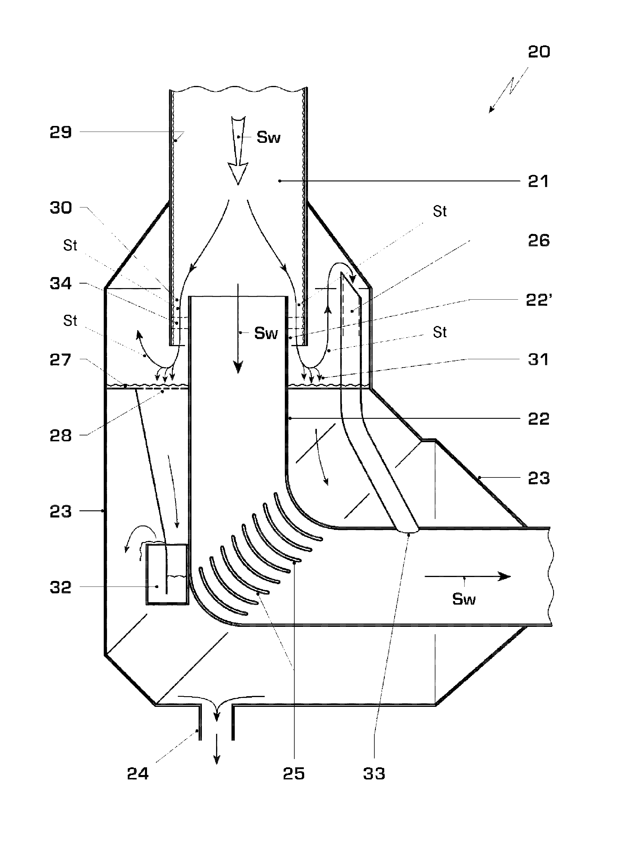
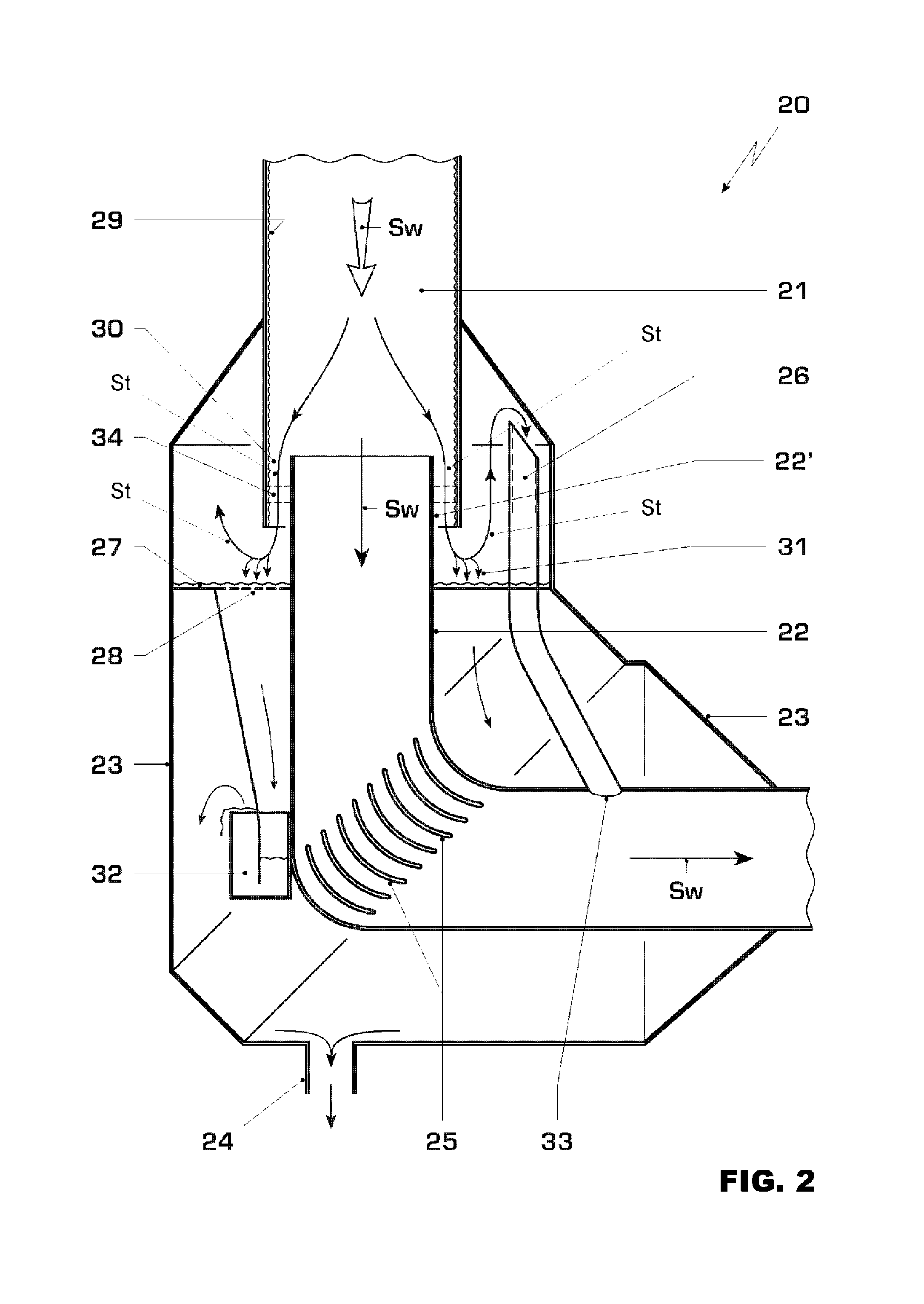
[0025]FIG. 2 shows an example of a preseparator 20 according to the A feed pipe 21 is again shown, through which operating steam SW from a high-pressure steam turbine flows in the direction of the arrow SW and reaches a steam transfer pipe 22 which is enclosed by the end of the feed pipe 21. The steam transfer pipe 22 finally leads from the preseparator into a (not shown) low-pressure steam turbine. Between the two pipes 21 and 22, there is a gap 30. In the gap 30, in one variant, a plurality of ribs 34 are arranged distributed over the circumference of the pipes 22 and 21. The separator has a housing 23 which, starting from the end of the feed pipe 21, encloses the steam transfer pipe 22 over a specified length together with a bend, and in a lower region has a water discharge pipe 24. The steam transfer pipe includes a bend of, for example, 90°, wherein a multiplicity of deflecting vanes 25 are arranged in the bend. A duct-like baffle 26 is arranged in the housing 23 and begins in...


PUM

PropertyMeasurementUnit
velocityaaaaaaaaaa
pressureaaaaaaaaaa
pressure dropaaaaaaaaaa

Abstract

A water preseparator (1) for steam turbine plants for the separation of water from the operating steam (SW) from a high-pressure steam turbine has a feed pipe (2) which extends over the starting section of a steam transfer pipe (4), wherein the two pipes are separated from each other by a gap (11) through which water (12) together with transporting steam (St) flow into a housing. The water discharges from the preseparator (1) via a water discharge pipe (6). the preseparator has structure for recycling of the transporting steam into the operating steam of the steam turbine plant, wherein this recycling structure has built-in fittings or a baffle (9) of the transporting steam, and also structure (4) for achieving a pressure drop, wherein the pressure drop exists between the gap (11) and a point at which the transporting steam is reintroduced into the operating steam (SW).

Description

[0001]This application is a Continuation of, and claims priority under 35 U.S.C. §120 to, International Application No. PCT / EP2007 / 058634, filed 20 Aug. 2007, and claims priority therethrough under 35 U.S.C. §§119, 365 to Swiss application no. 01493 / 06, filed 19 Sep. 2006, the entireties of both of which are incorporated by reference herein.BACKGROUND[0002]1. Field of Endeavor[0003]The invention relates to a water separator for steam turbine plants, especially to a preseparator.[0004]2. Brief Description of the Related Art[0005]During the transfer of operating steam from a high-pressure steam turbine into a low-pressure steam turbine, the operating steam is preferably directed through a high-velocity water separator. The separation of water from the operating steam before its reintroduction into the low-pressure steam turbine serves for reducing erosion damage on the turbine blading. In a high-velocity water separator, the separation takes place directly in the transfer pipe, wherei...

Claims


Application Information

Patent Timeline
Patent Type & Authority Patents(United States)
IPC IPC(8): B01D49/00
CPCF22B37/28B01D45/06Y10S55/23
Inventor STUCKI, CHRISTIAN PETER
Owner GENERAL ELECTRIC TECH GMBH
Why Eureka
Try Eureka