Lightguide plate and electronic device

a technology of electronic devices and lightguide plates, which is applied in the direction of lighting and heating apparatus, electric apparatus casings/cabinets/drawers, instruments, etc., can solve the problems of lightguide plate unsuitability for electronic devices, increase in production costs, and unsuitability of lightguide plates, so as to prevent light leakage

Inactive Publication Date: 2011-04-26
CITIZEN ELECTRONICS CO LTD
View PDF9 Cites 60 Cited by
  • Summary
  • Abstract
  • Description
  • Claims
  • Application Information

AI Technical Summary

Benefits of technology

[0014]The electronic device may further include a reflecting sheet for the connecting part that is disposed to cover at least one of the two opposite sides of the connecting part of the lightguide plate in the joint part. The reflecting sheet prevents leakage of light from the joint part.
[0029]In the foregoing electronic devices of various forms, a reflecting sheet for the connecting part may be disposed to cover at least one of two opposite sides of the connecting part of the lightguide plate in the joint part. The reflecting sheet prevents leakage of light from the joint part.

Problems solved by technology

This lightguide plate is, however, unsuitable for use in an electronic device in which a liquid crystal panel and a key operation part are curved, or in which these components are not in the same plane.
The lightguide plate is also unsuitable for use in a foldable electronic device in which a display part and a key operation part are mounted in respective casings, and the two casings are hinged to each other.
The electronic device according to the foregoing second conventional art requires two lightguide plates for a liquid crystal panel and a keyboard and needs a special arrangement to transfer light between the two lightguide plates at the hinged joint therebetween, resulting in an increase in the number of components and an increase in production cost.
Particularly, the hinged joint becomes complicated in structure, and the freedom for structural design and the reduction in thickness and weight are unfavorably limited to a considerable extent.

Method used


Image

  • Lightguide plate and electronic device
  • Lightguide plate and electronic device
  • Lightguide plate and electronic device

Examples


first embodiment

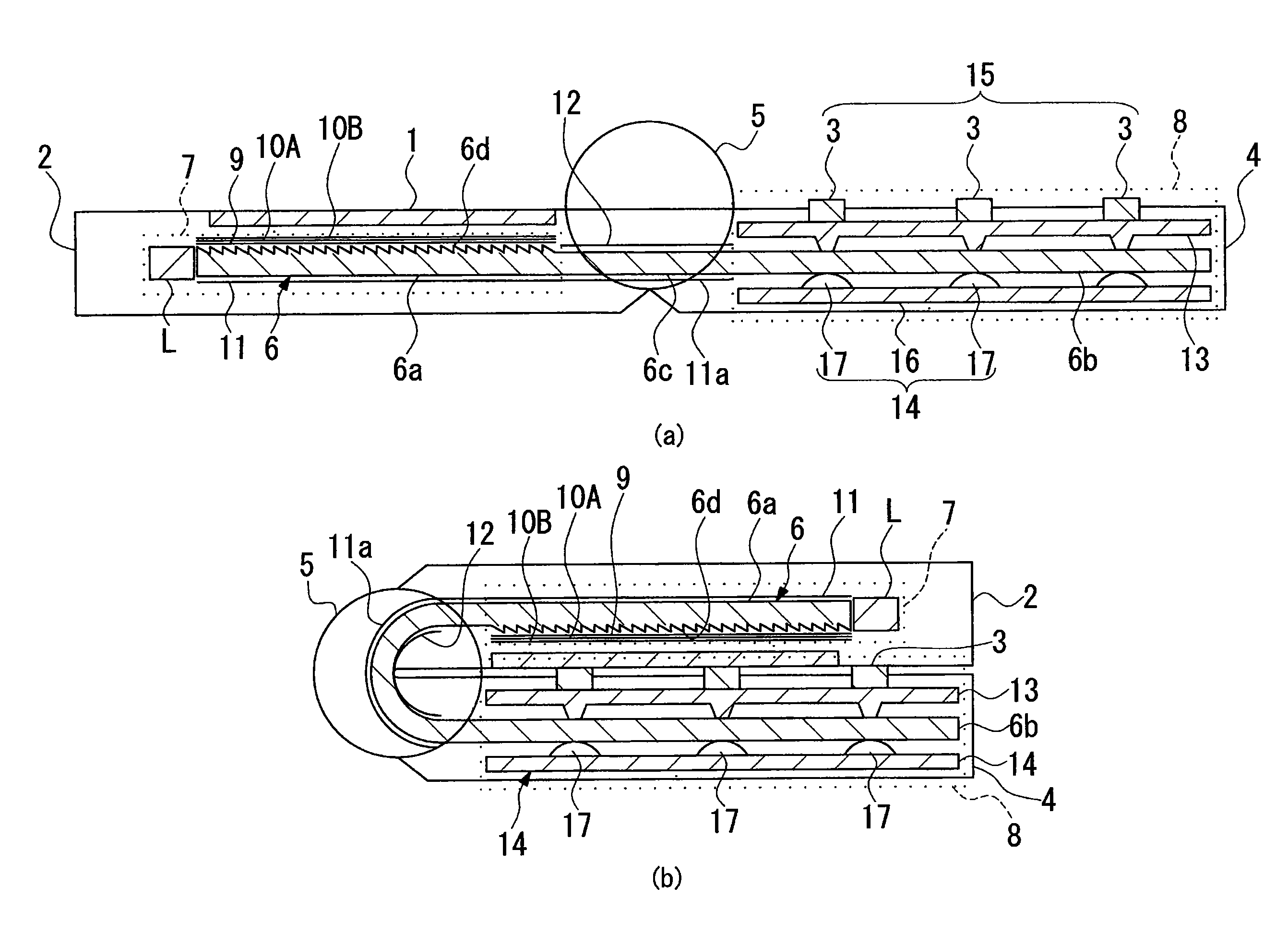
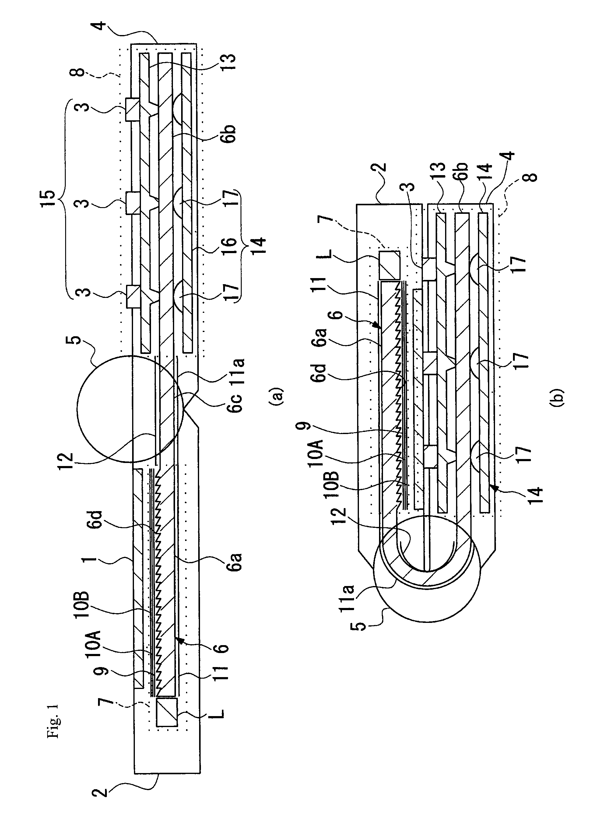
[0046]FIG. 1 shows an electronic device according to the present invention. The electronic device is a foldable, clamshell mobile phone having a display part 2 provided with a liquid crystal display panel (image display panel) 1, an operation part 4 provided with operation keys 3, and a joint part that connects together the display part 2 and the operation part 4. In this embodiment, the joint part is a hinged joint part 5 for hinged connection between the display part 2 and the operation part 4. The electronic device has LED light sources (light source) L, a backlight unit 7 having a lightguide plate 6 that receives light from the LED light sources L at an edge of the lightguide plate 6 and guides the light therethrough, and a key operation unit 8 that is a switch module provided in the operation part 4 and having the operation keys 3.

[0047]When the electronic device is in an unfolded position as shown in part (a) of FIG. 1, the liquid crystal display panel 1 and the operation keys...

second embodiment

[0074]It should be noted that the lightguide plate 6 is in the shape of a pliable film as a whole. Therefore, the lightguide plate 6 can be disposed in a curved form along the above-described curved configurations of the display part 22 and the operation part 24. In the second embodiment, the display illuminating part 6a and the key illuminating part 6b are also capable of guiding light therebetween irrespective of whether the mobile phone is folded or unfolded.

[0075]A third embodiment shown in FIG. 4 differs from the first embodiment as follows. In an electronic device of the third embodiment, a flat plate-shaped display part 32 and a flat plate-shaped operation part 34 are connected together through a hinged joint part 35 with a step therebetween when the electronic device is unfolded. When the electronic device is folded, the display part 32 and the operation part 34 are bent toward each other through the hinged joint part 35 into a U-shaped sectional configuration as a whole.

[00...

fourth embodiment

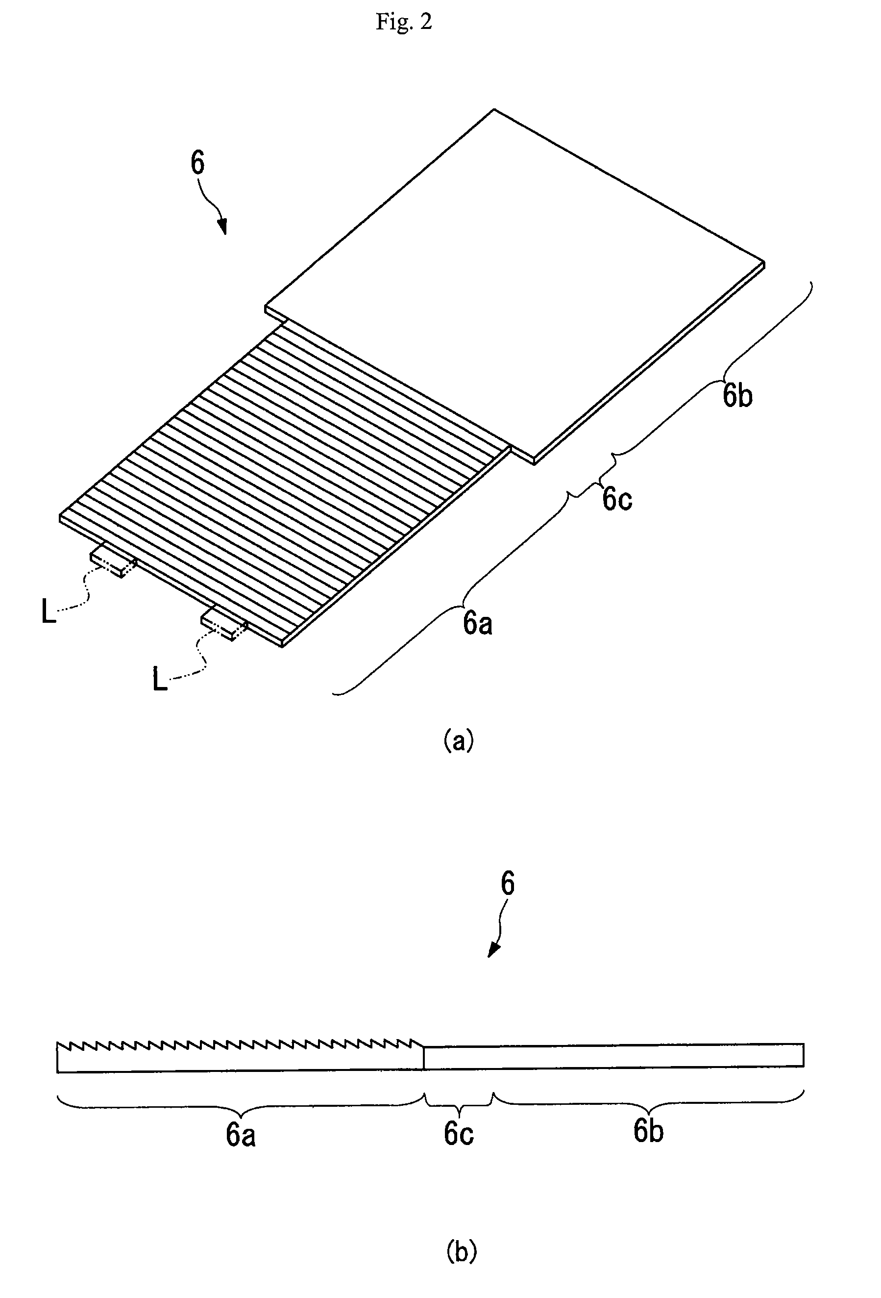
[0077]In an electronic device shown in FIG. 5, a display part 42 has an arcuate sectional configuration that is convexly curved at a side thereof closer to a liquid crystal display panel 1. The display part 42 is connected to a flat plate-shaped operation part 44 into one unit through a joint part 45. Constituent elements that are mounted in the display part 42, i.e. a liquid crystal display panel 1, a lightguide plate 6, a diffusing sheet 9, first and second prism sheets 10A and 10B, and a reflecting sheet 11, are curved with substantially the same curvature as that of the display part 42. The lightguide plate 6 is a thin sheet-shaped member as shown in FIG. 6, as in the case of the foregoing embodiments, before it is disposed in the electronic device.

[0078]An electronic device according to the fifth embodiment shown in FIG. 7 differs from the electronic device of the fourth embodiment in that a display part 52 has an arcuate sectional configuration that is concavely curved at a s...


PUM


Abstract

An electronic device includes a casing having a display part (2) provided with an image display panel (1), a operation part (4) provided with operation keys (3), and a joint part (5) that connects together the display part and the operation part, and a lightguide plate (6) disposed in the casing. The lightguide plate is an edge-light type lightguide plate having a display illuminating part (6a) illuminating the image display panel, a key illuminating part (6b) illuminating the operation keys, and a connecting part (6c) that connects together the display illuminating part and the key illuminating part and that guides light therebetween. The lightguide plate is deformable in accordance with the deformation of the casing.

Description

REFERENCE TO THE RELATED APPLICATIONS[0001]This application claims priority under 35 U.S.C. §119 to Japanese Patent application No. JP2007-224929 filed on Aug. 30, 2007 and Japanese Patent application No. JP2007-224932 filed on Aug. 30, 2007, the entire contents of which are hereby incorporated by reference.BACKGROUND OF THE INVENTION[0002]1. Field of the Invention[0003]The present invention relates to an electronic device, e.g. a mobile phone, having a lightguide plate used in a planar light source that illuminates a liquid crystal display panel and operation keys of the electronic device.[0004]2. Description of the Related Arts[0005]Liquid crystal display apparatus for image display are widely used in displays of mobile phones, personal digital assistants (PDAs), mobile personal computers (PCs), automatic teller machines (ATMs), etc. These liquid crystal display apparatus employ a backlight unit that applies illuminating light to a liquid crystal display panel from the back thereo...

Claims


Application Information

Patent Timeline
Patent Type & Authority Patents(United States)
IPC IPC(8): F21V7/04
CPCG02B6/0053G02B6/0073H04M1/22H04M1/0202G02B6/0088
Inventor ONIKIRI, AKIRAOKUWAKI, DAISAKUKAYANUMA, YASUAKI
Owner CITIZEN ELECTRONICS CO LTD
Why Eureka
Try Eureka