Optical pickup with support part having hole for being inserted with a projection part of a case
a technology of optical pickups and support parts, applied in the field of optical pickup objective lens actuators, can solve problems such as troublesome control of objective lens actuators, and achieve the effect of bringing unwanted resonance and high data transfer ra
- Summary
- Abstract
- Description
- Claims
- Application Information
AI Technical Summary
Benefits of technology
Problems solved by technology
Method used
Image
Examples
embodiment 1
[0027]Explanation will be made on a first embodiment according to the present invention, by referring to FIGS. 1, 2, 3, 4 and 7.
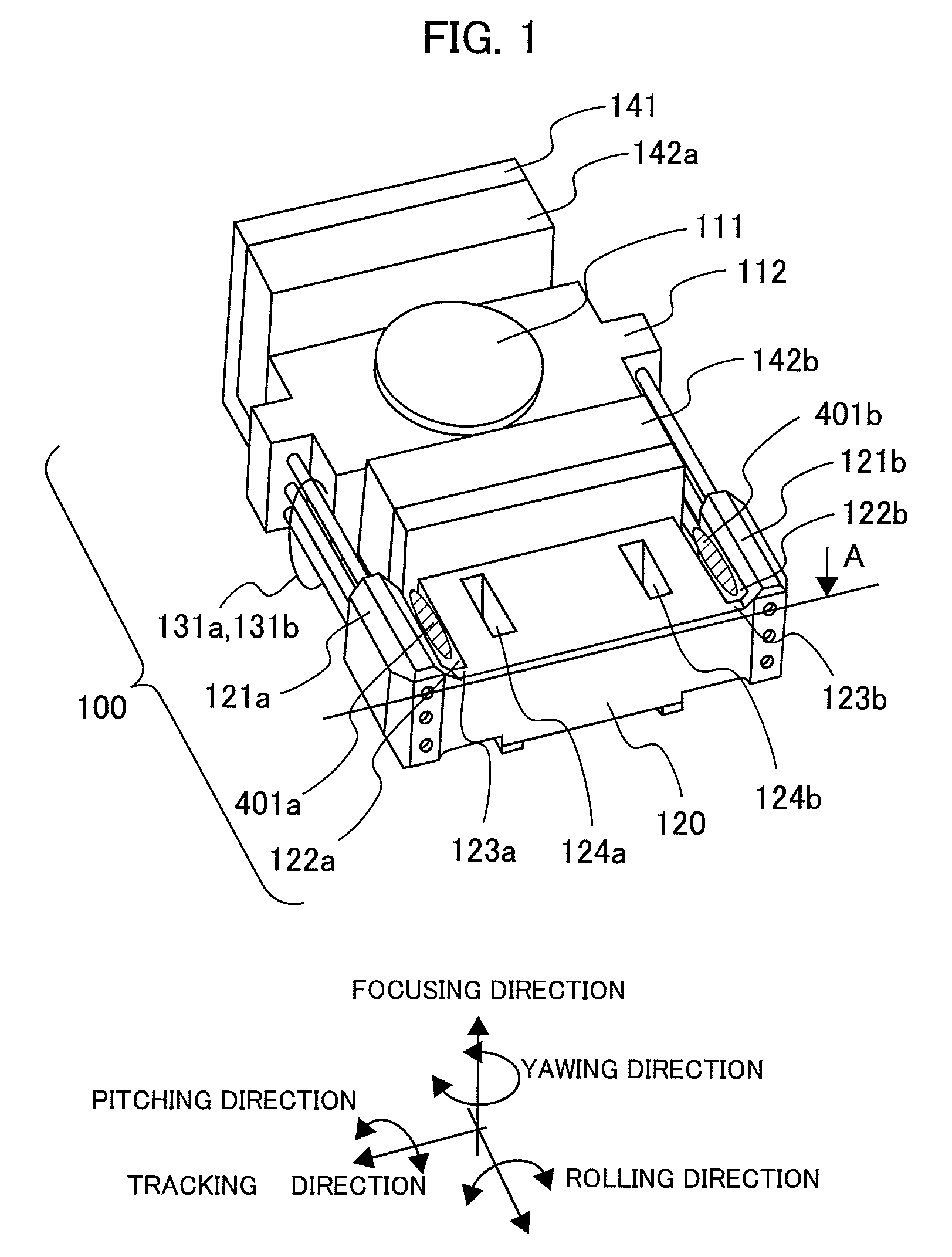
[0028]FIG. 1 is an outlook view for showing an objective lens actuator, according to the present embodiment.
[0029]FIG. 2 is a A-A cross-section view in FIG. 1, for showing the vicinity of an elastic support member support part, according to the present embodiment.
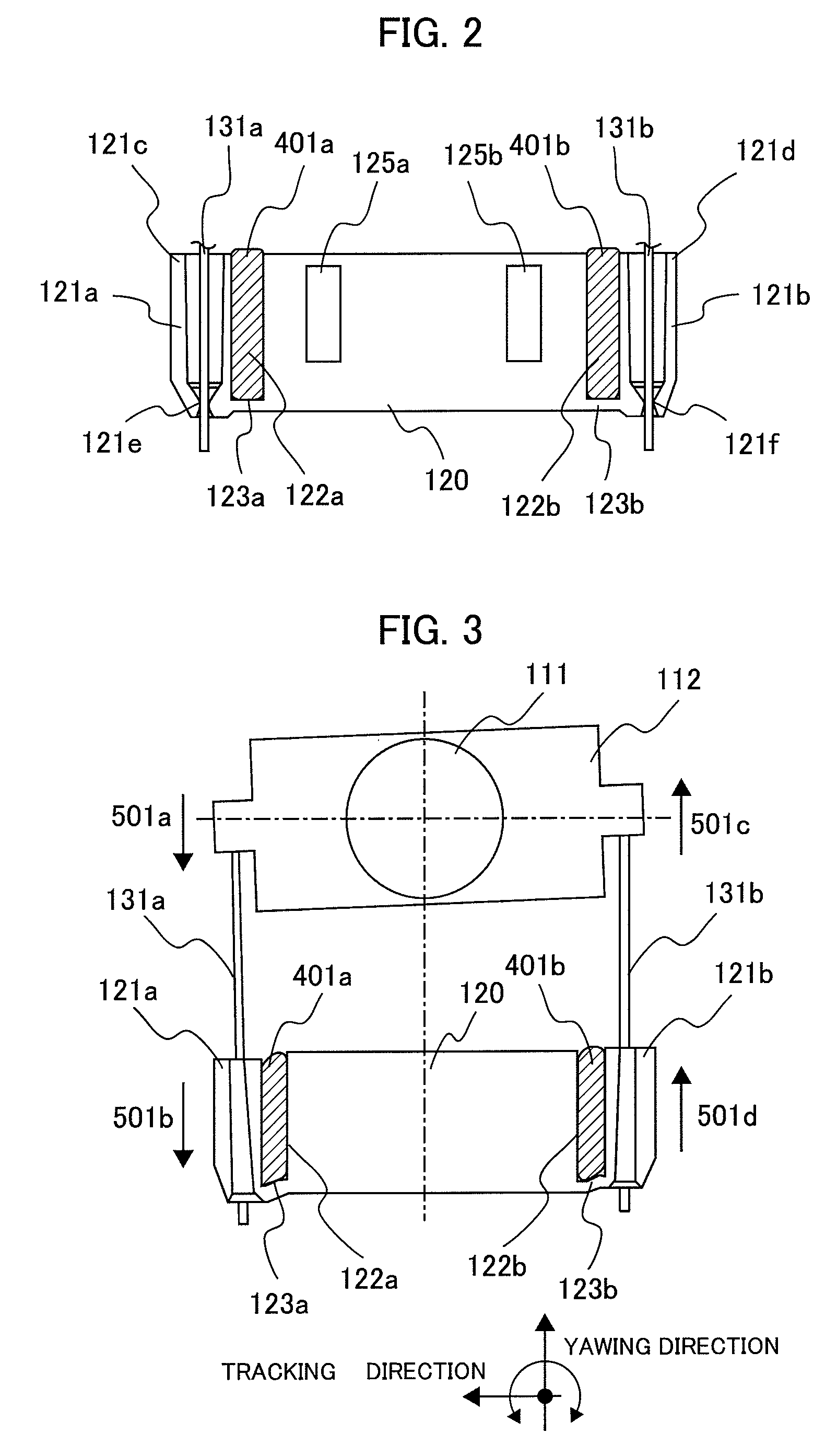
[0030]FIG. 3 is a view for showing the operations when a yawing vibration is generated, according to the present embodiment.
[0031]FIG. 4 is a view for showing the operations when a pitching vibration is generated, according to the present embodiment.
[0032]FIG. 7 is a graph for showing a relationship between a notch distance of the elastic support member support part and a phase disorder value of a yawing vibration.
[0033]The characteristic of the present embodiment lies in that a cutting area of a square shape is provided along with an axial direction of an elastic support member, within a member fo...
embodiment 2
[0050]FIG. 5 is a drawing for showing an outlook of mounting the objective lens actuator according to the present embodiment onto an optical pickup case.
[0051]The feature of the present embodiment lies in that a projection part formed on the optical pickup is inserted into a hole, which is provided on the objective lens actuator.
[0052]Hereinafter, the structures of the present embodiment will be shown.
[0053]In FIG. 5, the objective lens 111 is attached on the lens holder 112. The lens holder 112 is elastically supported on the wire support part 120, through the wires 131a and 131b, as the elastic support members, and is movable.
[0054]In this manner, the objective lens 111 can focus the laser light onto the disc not shown in the figure. The lens holder 112 can move or displace in the movable directions, i.e., the focus, tracking and radial tilt directions, largely, but as will be mentioned later, a part of the wire support part 120 connecting with the wire can also move or displace i...
embodiment 3
[0060]Explanation will be made on a third embodiment of the present invention, by referring to FIG. 6.
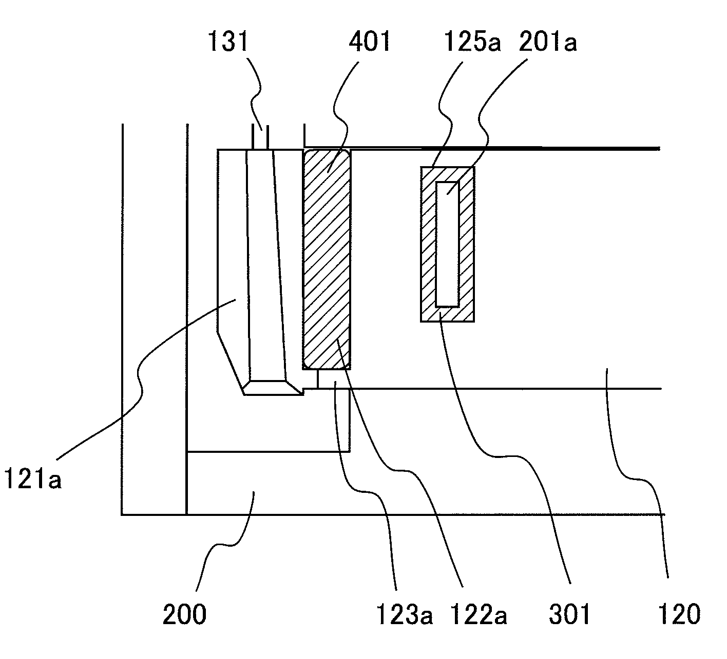
[0061]FIG. 6 is a view for showing the connection part between the wire support part and the optical pickup case, enlargedly.
[0062]The feature of the present embodiment lies in that an adhesive having attenuation or damping function is disposed at the connection part between the wire support part and the optical pickup case according to the embodiment 2.
[0063]Explanation will be made on the present embodiment by referring to FIG. 6.
[0064]In FIG. 6, the connection part between the wire support part 120 and the optical pickup case 200 is connected by an insertion hole 125a, which is provided on the wire support part 120, and a projection part 201a, which is provided on the optical pickup case 200. The size of the insertion hole 125a formed is determined to be small comparing to the projection part 201a. Accordingly, when connecting the wire support part 120 with the optical pickup cas...
PUM
| Property | Measurement | Unit |
|---|---|---|
| density | aaaaa | aaaaa |
| elastic | aaaaa | aaaaa |
| elasticity | aaaaa | aaaaa |
Abstract
Description
Claims
Application Information
 - R&D
- Intellectual Property
- Life Sciences
- Materials
- Tech Scout
- Unparalleled Data Quality
- Higher Quality Content
- 60% Fewer Hallucinations
Browse by: Latest US Patents, China's latest patents, Technical Efficacy Thesaurus, Application Domain, Technology Topic, Popular Technical Reports.
© 2025 PatSnap. All rights reserved.Legal|Privacy policy|Modern Slavery Act Transparency Statement|Sitemap|About US| Contact US: help@patsnap.com


