Al technical title is built by PatSnap Al team. It summarizes the technical point description of the patent document.
a magnetic flakes and apparatus technology, applied in the field of apparatus for aligning or orienting magnetic flakes, can solve the problems of high disadvantage, unfavorable high-speed printing process, and widely known optically variable devices intended to be noticed
Active Publication Date: 2011-05-03
VIAVI SOLUTIONS INC
View PDF229 Cites 19 Cited by
Summary
Abstract
Description
Claims
Application Information
AI Technical Summary
This helps you quickly interpret patents by identifying the three key elements:
Problems solved by technology
Method used
Benefits of technology
[0027]In accordance with another aspect of this invention, the one or more permanent magnets comprise a first magnet that is rotatably positioned within one of the cavities, and a means for spinning the first magnet within the cavity during the printing process for providing an illusion of depth to the image formed by the first magnet on the substrate in the linear printing process.
Problems solved by technology
Unfortunately, some optically variable devices that are intended to be noticed are not widely known because the optically variable aspect of the device is not sufficiently dramatic.
While these approaches describe methods and apparatus for formation of three-dimensional-like images in paint layers, they are not suitable for high-speed printing processes because they are essentially batch processes.
First, the device of Miklos et al can magnetically imprint only substantially two-dimensional patterns copying geometrical arrangements of the magnets mounted on the cylinder, each magnet essentially providing a “dot” in the pattern imprinted in the magnetic layer. It would be very difficult if at all possible to use this technology to provide predetermined substantially three-dimensional (3D) or complex arrangements of magnetic flakes that are required for providing optical images with variable or illusive optical effects, such as rolling objects and images with illusion of depth.
Second, in the device of Miklos et al, the magnets are mounted on the outer surface of the cylinder, and are therefore projecting therefrom. This can be highly disadvantageous in contact printing, when the cylinder is in contact, possibly under some pressure, with the sheet whereupon the magnetic layer is disposed.
Third, since in the device of Miklos et al, the magnets are fixedly attached to the surface of the cylinder, it cannot be used to form illusive images that can be produced by spinning magnets, as described in co-pending U.S. patent application Ser. No. 11 / 278,600, filed Apr. 4, 2006, the disclosure of which is incorporated herein by reference.
The steps required to produce the engravings in the permanent magnetic material can be cumbersome; furthermore, the printing with the engraved surfaces is generally directed to reproducing the engraved indicia or drawings, and is limited in terms of optical effects it can produce.
Method used
Image
Click on the blue label to locate the original text in one second.
Reading with bidirectional positioning of images and text.
Examples
Embodiment Construction
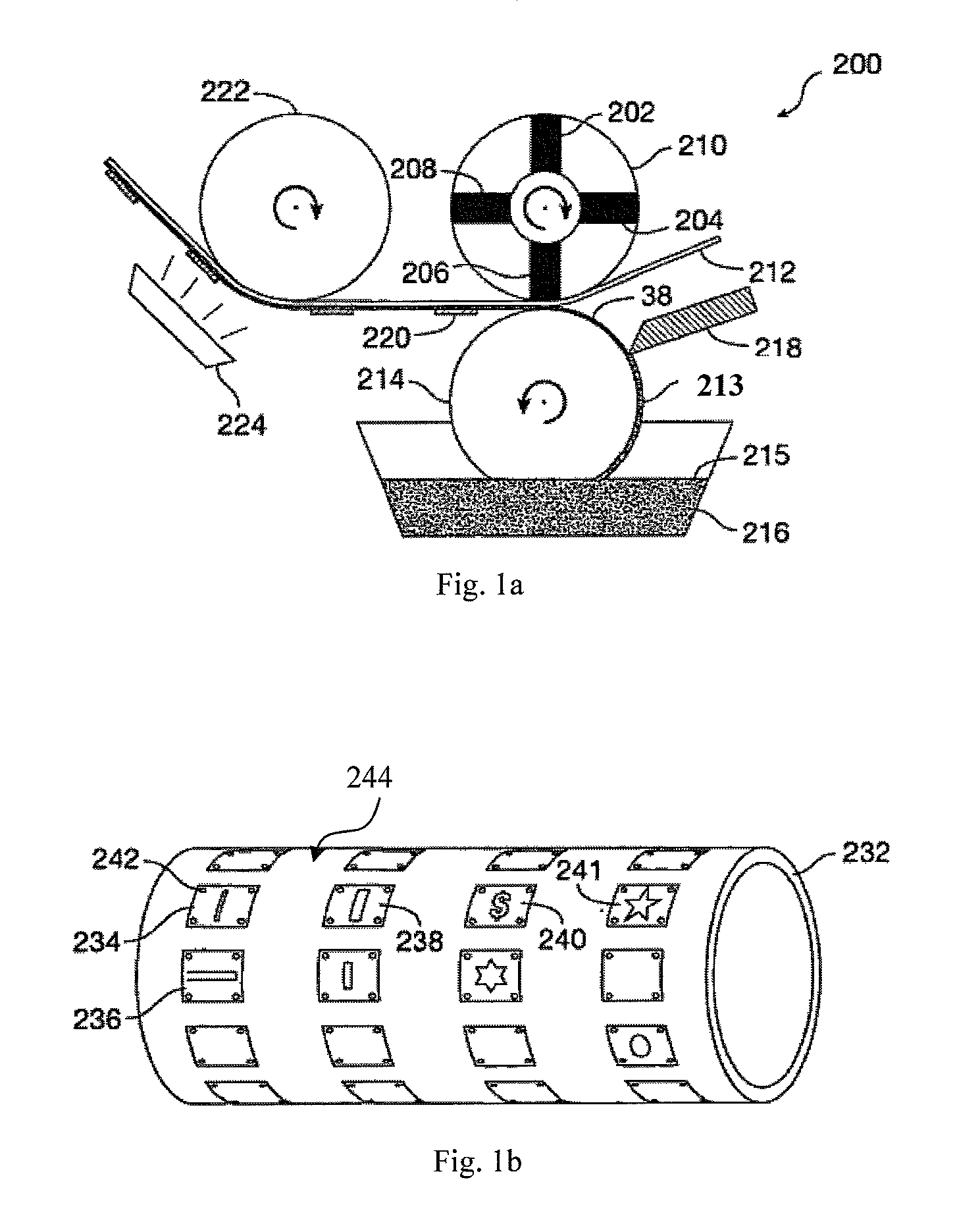
[0058]Exemplary embodiments of the apparatus of the present invention for orienting magnetic flakes in a paint, ink or other fluid carrier printed on a substrate in a continuous linear process will now be described, first with reference to FIGS. 1a-1c.
[0059]FIG. 1a is a simplified side-view schematic of a portion of a printing apparatus 200 according to an embodiment of the present invention. An important part of the apparatus of the present invention is a magnetic roller, which is understood herein as a roller having magnetized portions and non-magnetized or differently magnetized portions. The term “magnetized portions” in relation to the roller of the present invention is used herein to mean a permanent magnet imbedded in the roller, or a selectively magnetized region of the roller adjacent to its surface, or an alternatively formed portion of a roller that has a pre-determined magnetization different from magnetization of surrounding it areas of the roller, so as to form a pre-...
PUM
Abstract
A printing apparatus includes a magnetic rotatable roller with a smooth even outer surface for aligning magnetic flakes in a carrier, such as an ink vehicle or a paint vehicle to create optically variable images in a high-speed, linear printing operation. Images can provide security features on high-value documents, such as bank notes. Magnetic flakes in the ink are aligned using magnetic portions of the roller, that can be formed by permanent magnets embedded in a non-magnetic roller body, or selectively magnetized portions of a flexible magnetic cover of the roller. In some embodiments, the roller is assembled for a plurality of interchangeable sections, which can include spinning magnets. Selected orientation of the magnetic pigment flakes can achieve a variety of illusive optical effects that are useful for decorative or security applications.
Description
CROSS-REFERENCE TO RELATED APPLICATIONS[0001]The present invention claims priority from U.S. Provisional Patent Application Ser. No. 60 / 759,356, filed Jan. 17, 2006, entitled “Magnetic Rollers For Alignment Of Dispersed Magnetic Particles And Patterned Optical Security Image Device With Illusion Of Depth”, and U.S. Provisional Patent Application Ser. No. 60 / 777,086, filed Feb. 27, 2006, the disclosures of which are incorporated herein by reference in it entirety for all purposes.[0002]This patent application is a continuation-in-part application of U.S. patent application Ser. No. 11 / 552,219, filed Oct. 24, 2006, and U.S. patent application Ser. No. 11 / 278,600, filed Apr. 4, 2006, which claims priority from U.S. Provisional Patent Application Ser. No. 60 / 668,852, filed Apr. 6, 2005, both of which are continuation-in-part applications of U.S. patent application Ser. No. 11 / 313,165, filed Dec. 20, 2005 now U.S. Pat. No. 7,604,855, which is a continuation-in-part application of U.S. pa...
Claims
Application Information
Patent Timeline
Application Date:The date an application was filed.
Publication Date:The date a patent or application was officially published.
First Publication Date:The earliest publication date of a patent with the same application number.
Issue Date:Publication date of the patent grant document.
PCT Entry Date:The Entry date of PCT National Phase.
Estimated Expiry Date:The statutory expiry date of a patent right according to the Patent Law, and it is the longest term of protection that the patent right can achieve without the termination of the patent right due to other reasons(Term extension factor has been taken into account ).
Invalid Date:Actual expiry date is based on effective date or publication date of legal transaction data of invalid patent.