Process for making swaged lighting holes in planar areas of preimpregnated composite parts

a composite part and lighting hole technology, applied in the field of making swaged lighting holes in the planar area of preimpregnated composite parts, can solve the problems of fabric, poor structural properties, and high cost of process, and achieve the effect of facilitating the slippage of fibers

Inactive Publication Date: 2011-05-03
AIRBUS OPERATIONS SL
View PDF10 Cites 2 Cited by
  • Summary
  • Abstract
  • Description
  • Claims
  • Application Information

AI Technical Summary

Benefits of technology

[0011]The process may additionally include the application of heat to the part while carrying out the process to achieve a temperature in the resin facilitating the slippage of the fibers of the material and a final cooling step if its handling is required immediately after making the swaged lighting hole.

Problems solved by technology

This process is expensive, since it is completely manual and requires the use of materials that can adapt to the complex geometry of the swaged lighting hole without forming wrinkles.
The most adaptable type of material is fabric, which, compared with the tape, is more expensive and has worse structural properties.

Method used


Image

  • Process for making swaged lighting holes in planar areas of preimpregnated composite parts
  • Process for making swaged lighting holes in planar areas of preimpregnated composite parts
  • Process for making swaged lighting holes in planar areas of preimpregnated composite parts

Examples


Embodiment Construction

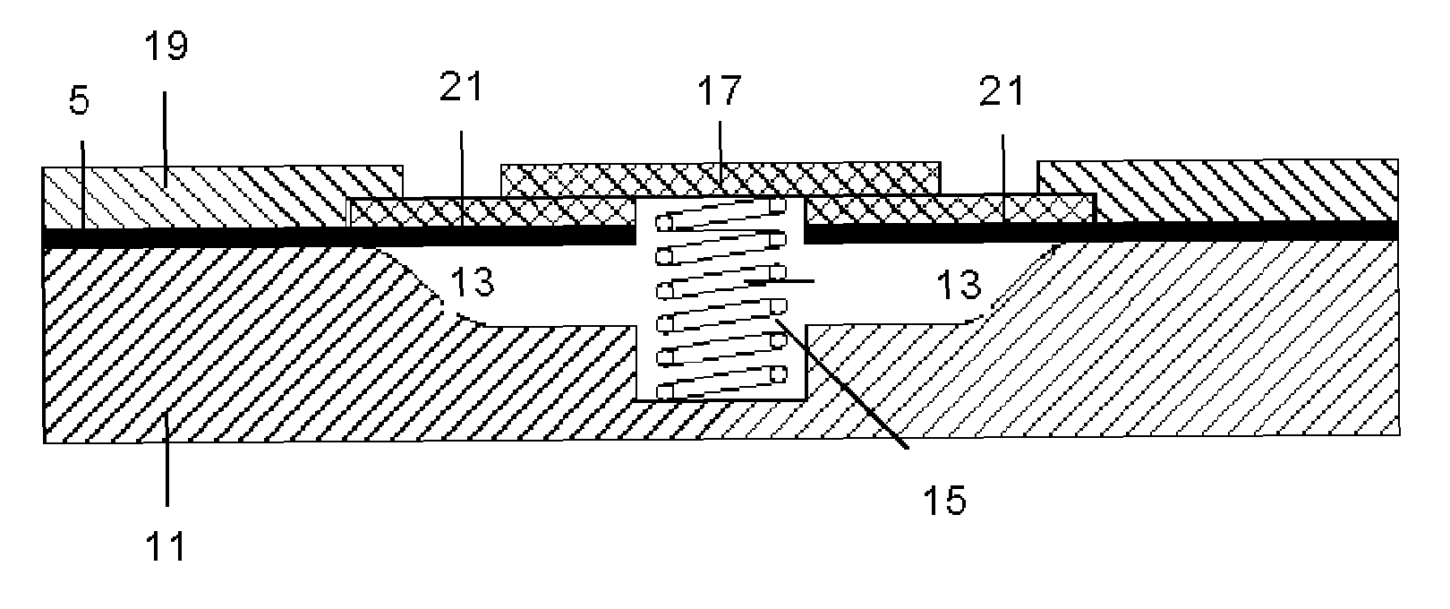
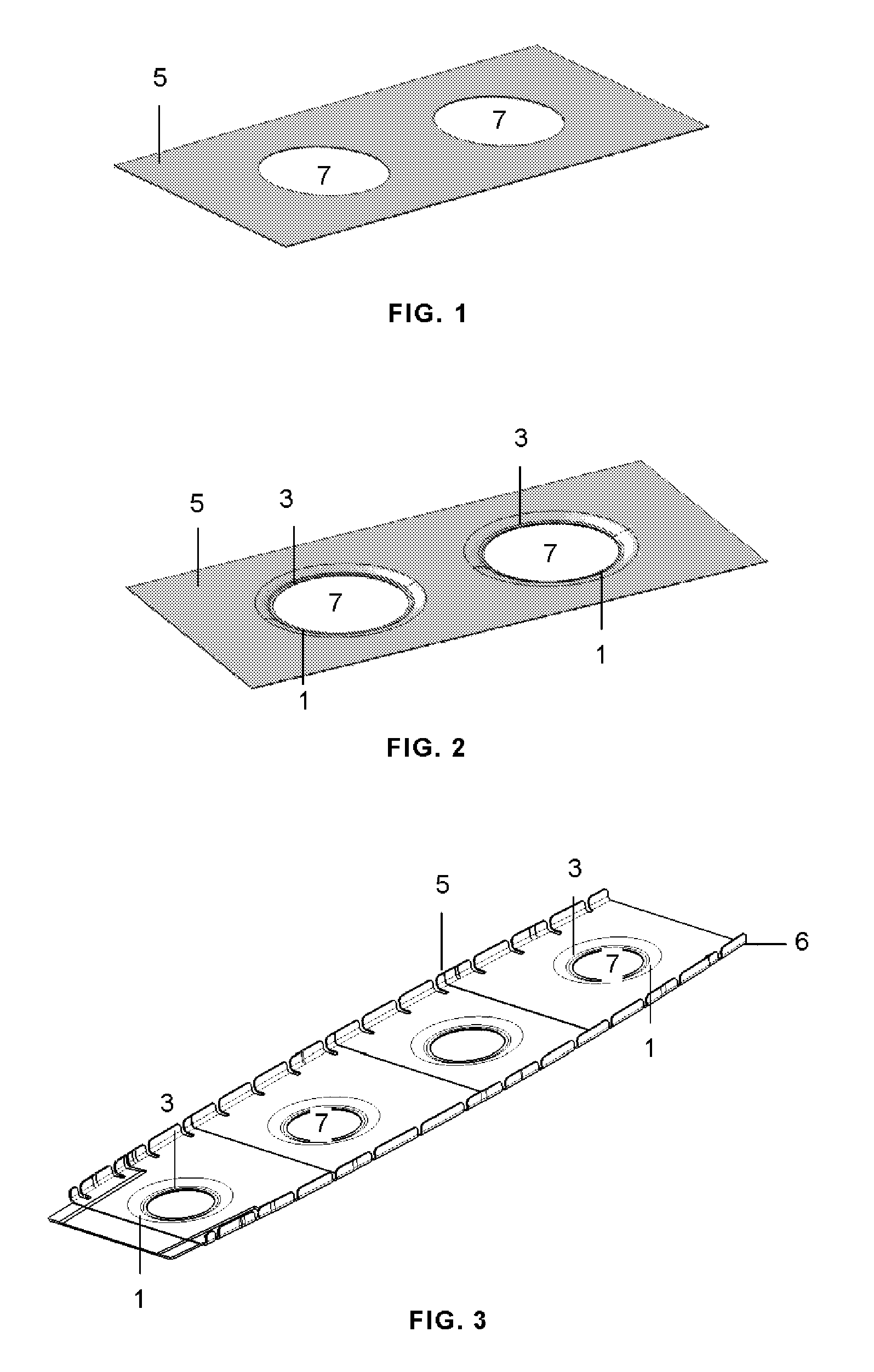
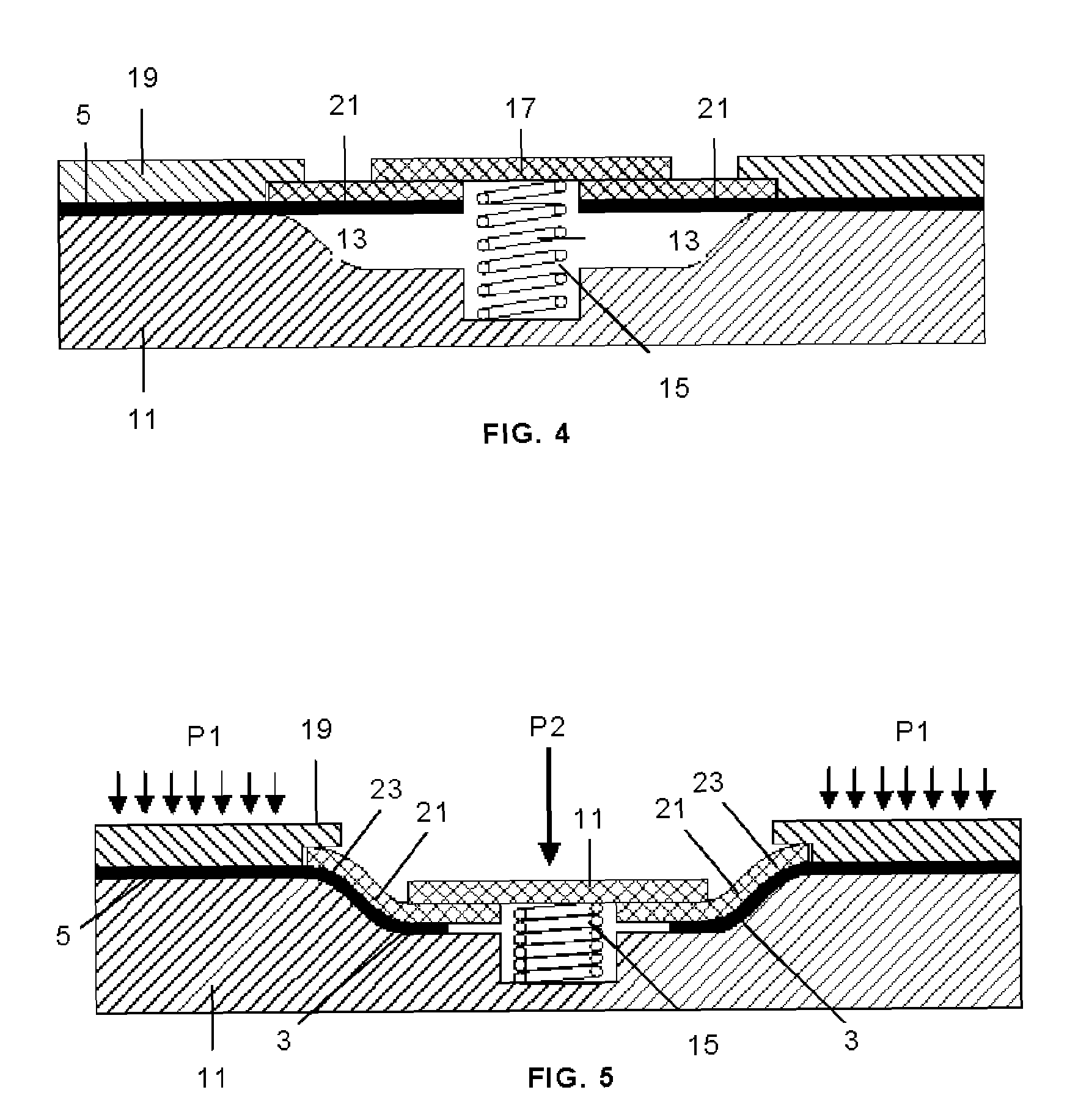
[0018]An embodiment of the process according to the invention for carrying out the swaged lighting hole 1 consisting, as is shown in the cases represented in FIGS. 2 and 3, of a recess of an area 3 of the part 5 surrounding the opening 7, with an S-shaped contour, is described below. As the person skilled in the art will understand, the swaged lighting hole may have another shape.

[0019]The swaged lighting holes 3 are made in a planar or quasi-planar area of the part 5, but the latter may have a non-planar shape like the part 5 shown in FIG. 3, which corresponds to a rib with a C-shaped section, in which the flanges 6 have been formed prior to making the swaging according to this invention.

[0020]The part 5 is covered with a thin plastic film (not represented) to prevent it from adhering to the tooling of the swaged lighting hole process and is placed, suitably centering it, on a female tooling 11 the top side of which reproduces the shape that the part must be given during the swagin...


PUM

PropertyMeasurementUnit
pressureaaaaaaaaaa
resistanceaaaaaaaaaa
shapeaaaaaaaaaa

Abstract

The invention relates to a process for making swaged lighting holes (1) in planar areas of parts (5) made of preimpregnated composite, by means of which the part (5) is arranged between a female tooling (11) with the final shape of the bottom side of the swaged part and a caul plate (19) with the final shape of the top side of the swaged part, except in an area (3) which must be swaged, pressure P1 is applied on the caul plate (19) in the area of the part (5) that must be maintained substantially planar, and pressure P2 is applied by means of a male tooling (17) on the area (3) of the part (5) which must be swaged at a forward speed allowing the flow of the resin during the slippage of the fibers of the material so that it may deform, adapting to the final shape of the female tooling (11).

Description

FIELD OF THE INVENTION[0001]This invention relates to a process for making swaged lighting holes in planar areas of preimpregnated composite parts, and particularly in parts made by means of automatic laying machines.BACKGROUND OF THE INVENTION[0002]The use of swaged lighting holes in structural parts is common in order to achieve an increase of stiffness without increasing the weight and with a minimum cost.[0003]The processes for making swaged lighting holes on sheet metal are common in industry and achieve the desired deformation of the sheet by means of its plastic deformation.[0004]In the case of composite parts formed with stiff continuous fibers, however the mechanism allowing the adaptation to the desired shape of the swaged lighting hole is based on the relative slippage of fibers.[0005]In parts made with composites, the traditional process for making swaged lighting holes consists of manually laminating each layer, adapting it to the geometry of the swaged lighting hole. T...

Claims


Application Information

Patent Timeline
Patent Type & Authority Patents(United States)
IPC IPC(8): B29C53/04B29C70/54
CPCB29C51/12B29C70/342B29C70/545B29C70/541Y10T156/1039B29C70/549
Inventor CANO CEDIEL, DAVIDMENENDEZ MARTIN, JOSE MANUELPEREZ PASTOR, AUGUSTODURAN QUIROGA, ANTONIONOGUEROLES VINES, PEDRO
Owner AIRBUS OPERATIONS SL
Why Eureka
Try Eureka