Apparatus for initializing and method of manufacturing optical disc, and initialization reference plate

a technology for optical discs and reference plates, which is applied in the field of optical discs, apparatuses for initializing and manufacturing optical discs, and initialization reference plates. it can solve problems such as complicated configuration

Inactive Publication Date: 2011-05-03
SONY CORP
View PDF8 Cites 7 Cited by
  • Summary
  • Abstract
  • Description
  • Claims
  • Application Information

AI Technical Summary

Benefits of technology

[0013]A technique has thus been desired that can irradiate a target mark position PG in the recording layer DKw with the light beam LB without irradiating the reflecting layer DKs with the servo light beam LS.
[0020]Consequently, the initialization reference plate makes it possible to form a recording mark intended for servo control in the servo mark area of the optical disc with reference to the reference part, so that servo control can be performed by using the recording mark intended for servo control when recording information on the optical disc in which the recording mark intended for servo control is formed.
[0021]According to the present invention, it is possible to form a recording mark intended for servo control in the servo mark area of the optical disc with reference to the reference part, so that servo control can be performed by using the recording mark intended for servo control when recording information on the optical disc in which the recording mark intended for servo control is formed. This makes it possible to achieve an apparatus for initializing and a method of manufacturing an optical disc that are capable of manufacturing an optical disc in whose recording layer a target mark position can be irradiated with an information light beam without a reflecting layer being irradiated with a servo light beam, and an initialization reference plate for use in manufacturing the optical disc.

Problems solved by technology

This requires that the optical disc apparatus provide separate optical paths for the light beam LB and the servo light beam LS, respectively, which complicates the configuration.

Method used


Image

  • Apparatus for initializing and method of manufacturing optical disc, and initialization reference plate
  • Apparatus for initializing and method of manufacturing optical disc, and initialization reference plate
  • Apparatus for initializing and method of manufacturing optical disc, and initialization reference plate

Examples


first embodiment

(1) First Embodiment

(1-1) Configuration of Optical Disc

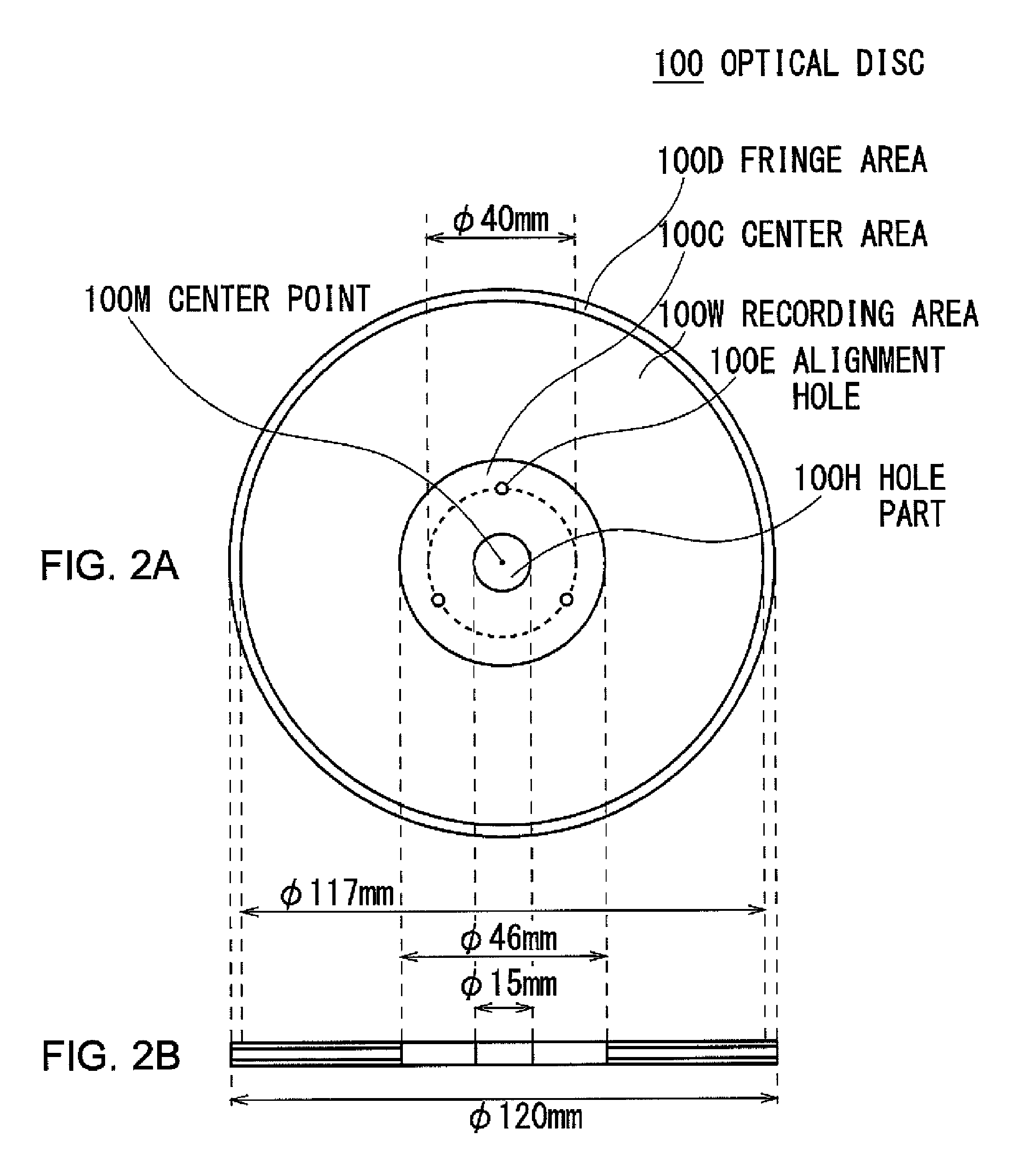
[0053]Initially, description will be given of the optical disc 100 which is used as an optical information recording medium according to a first embodiment of the present invention. As shown in the external view of FIG. 2A and the cross-sectional view of FIG. 2B, the optical disc 100 is formed in a disc shape having a diameter of approximately 120 mm as a whole, like hitherto known CD, DVD, and BD. A hole part 100H of approximately 15 mm in diameter is made in the center.

[0054]The optical disc 100 is provided with a center area 100C, a recording area 100W, and a fringe area 100D from the hole part 100H to the periphery. More specifically, the center area 100C, the recording area 100W, and the fringe area 100D of the optical disc 100 are formed with outside diameters of approximately 46 mm, approximately 117 mm, and approximately 120 mm, respectively. Information is only recorded on the recording area 100W which ranges from appro...

second embodiment

(2) Second Embodiment

[0208]FIGS. 22A to 28 show a second embodiment. Parts corresponding to those of the first embodiment shown in FIGS. 2 to 21 will be designated by like reference numerals. The second embodiment differs from the first embodiment in the method of fixing an optical disc 110 and an initialization reference plate 220, and in that the servo mark areas As are formed only on the radially inner side of the optical disc 110.

(2-1) Configuration of Optical Disc

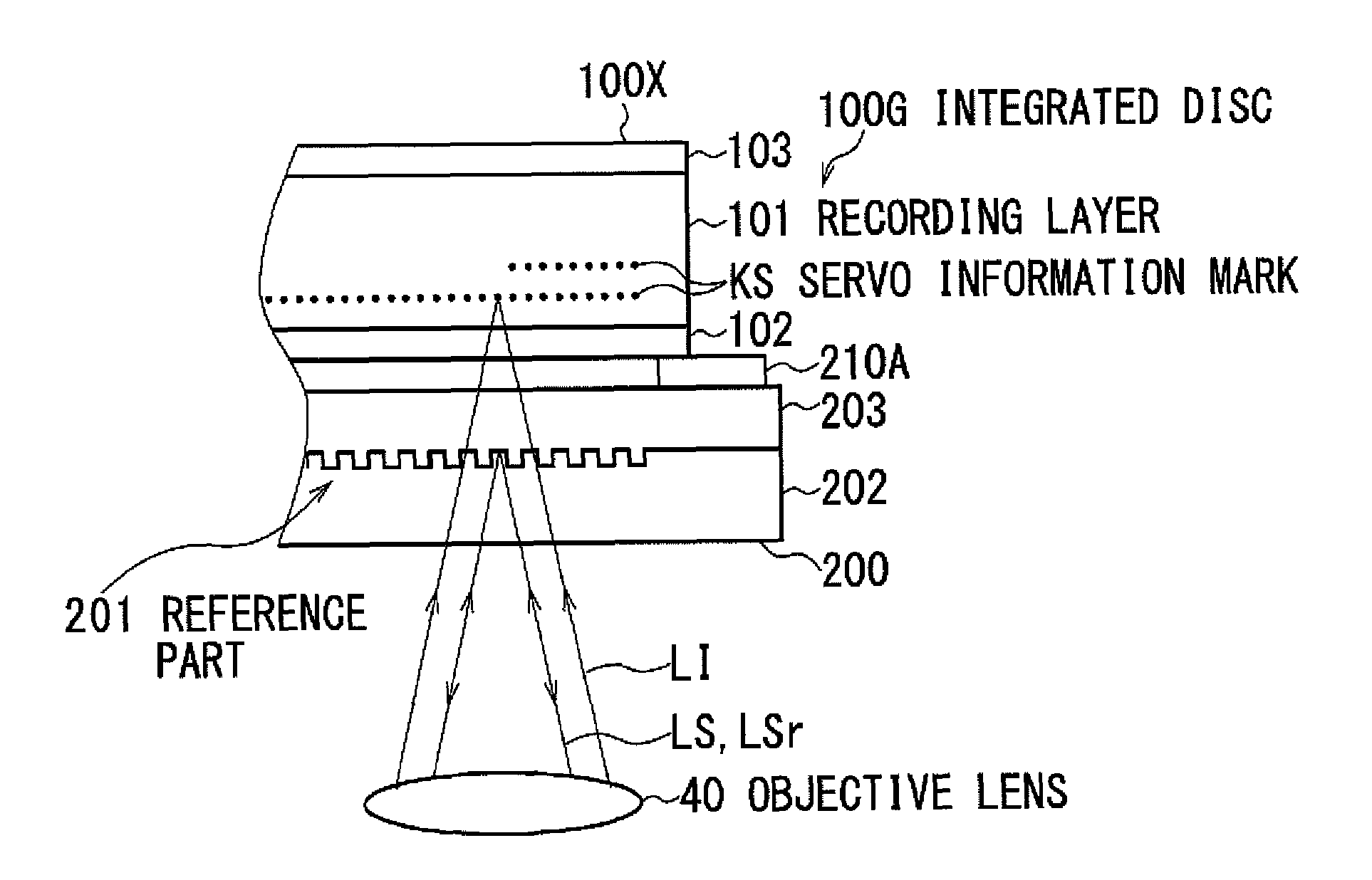
[0209]As shown in FIGS. 22A and 22B, the optical disc 110 is formed by sandwiching a recording layer 111 of uniform configuration between substrates 112 and 113 like the optical disc 100 according to the first embodiment. A hole part 110H intended for chucking is formed in the center.

[0210]As shown in FIG. 22A, the optical disc 110 is provided with servo information marks KS in advance, at a radially inner portion (hereinafter referred to as a lead-in area RA) of each of the mark layers Y to be formed in the recording ...


PUM

PropertyMeasurementUnit
diameteraaaaaaaaaa
diameteraaaaaaaaaa
areaaaaaaaaaaa

Abstract

An embodiment of the present invention includes rotating an integrated disc formed by temporarily fixing an initialization reference plate to an uninitialized optical disc that is an optical disc to be irradiated with a light beam of light having a predetermined or higher intensity to record information as a recording mark. The initialization reference plate has a reference part that reflects at least a part of a servo light beam of servo light intended for servo control. The reference part contains information that indicates the position of a track of the optical disc for the recording mark to be formed on, in the form of a track of pit-and-projection pattern.

Description

BACKGROUND OF THE INVENTION[0001]1. Field of the Invention[0002]The present invention relates to an optical disc, an apparatus for initializing and a method of manufacturing an optical disc, and an initialization reference plate, and is suitably applicable, for example, to an optical disc apparatus which records a plurality of recording marks on a single recording layer in a thickness direction.[0003]2. Description of the Related Art[0004]Optical disc apparatuses that irradiate an optical disc such as compact disc (CD), digital versatile disc (DVD), and Blu-ray Disc (registered trademark, referred to as BD, hereinafter) with a light beam and read the reflected light for information reproduction have been in widespread use.[0005]Such hitherto known optical disc apparatuses also perform information recording by irradiating the optical disc with a light beam so that the optical disc causes a local change in reflectance etc.[0006]For the optical disc, it is known that a light spot of ap...

Claims


Application Information

Patent Timeline
Patent Type & Authority Patents(United States)
IPC IPC(8): G11B7/00
CPCG11B7/26G11B7/00745G11B7/00452G11B2007/0013
Inventor FUJITA, GOROSAITO, KIMIHIRO
Owner SONY CORP
Why Eureka
Try Eureka