
Single fiber optical links for simultaneous data and power transmission

Active Publication Date: 2011-05-10
HRL LAB
View PDF11 Cites 80 Cited by
  • Summary
  • Abstract
  • Description
  • Claims
  • Application Information

AI Technical Summary

Benefits of technology

In one embodiment, provided is a means for combining a high power optical signal and a low power data signal with wavelength selective dire

Problems solved by technology

Use of these traditional means imposes a variety of limitations on the system operation.
These limitations include system weight and size,

Method used


Image

  • Single fiber optical links for simultaneous data and power transmission
  • Single fiber optical links for simultaneous data and power transmission
  • Single fiber optical links for simultaneous data and power transmission

Examples


Example

The optical transmission of power would be useful for applications such as unattended sensors or unmanned vehicles need to operate much longer than is possible with batteries, and where power transmission by metallic wire is unacceptable because of weight or electromagnetic compatibility issues. In various implementations of the present invention, a clad optical fiber is used to transmit both power and data.

The prior art utilizes double clad fibers for amplifiers and lasers by injecting a short wavelength optical signal (980 nm) into the cladding, which interacts with and stimulates an active dopant in the fiber core to provide coherent energy, and hence gain, to a longer wavelength optical input signal (1300 or 1550 nm) in the core. In such applications the wavelength λ1 in the core is greater than the wavelength λ2 in the cladding Thus, for fiber optical amplifiers and lasers λ1>λ2.

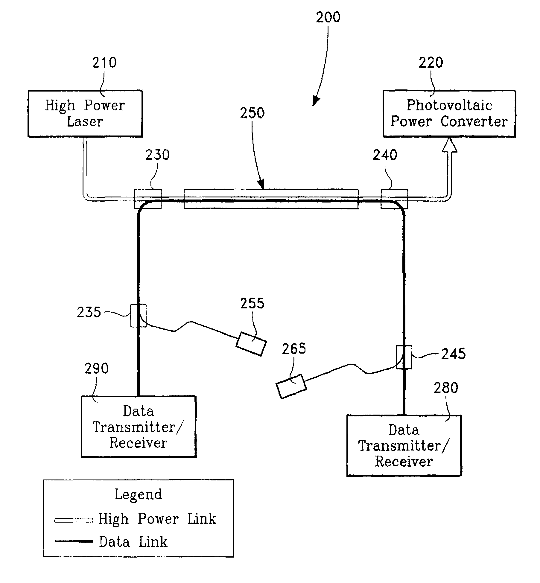
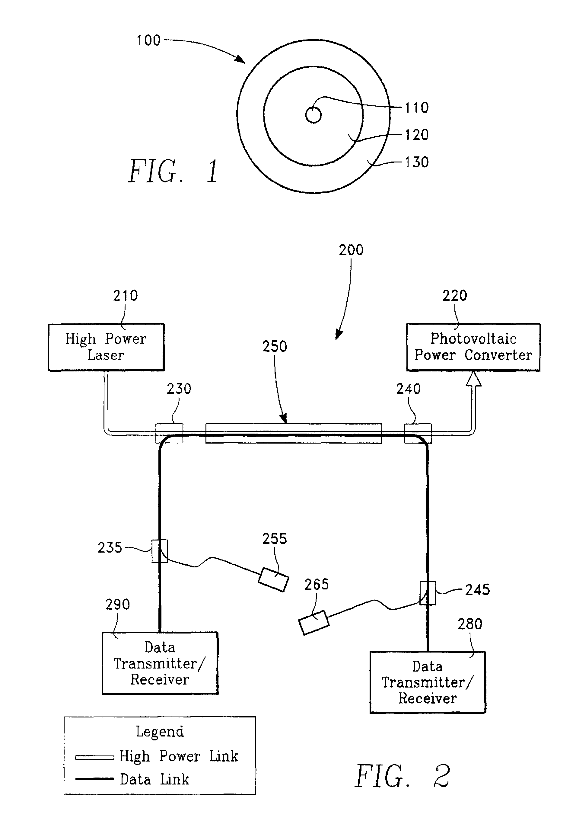
In a present implementation, a double clad fiber 100 shown in FIG. 1 is used is used in a totally di...


PUM


Abstract

In one embodiment, a fiber optic link includes a combined optical link for transmitting high optical power and wide bandwidth signal through a single optical fiber. In one embodiment, a means is provided for combining a high power optical signal and a low power data signal with wavelength selective directional couplers so as to inhibit the low power data transmitter and the low power data receiver from being overloaded with too much power. In one implementation, a method of using double clad fiber is provided, which includes transmitting an optical data signal at an optical data wavelength along an inner core, the inner core being single mode at the optical data wavelength and simultaneously transmitting an optical power signal at a optical power wavelength through a cladding, the cladding serving as a multimode core for a power optical link at the optical power wavelength.

Description

BACKGROUNDUnattended sensors, micro- or miniature-air vehicles (MAVs) and Unmanned Ground Vehicles (UGVs) will require more energy than batteries can supply. The delivery of high power through an optical fiber to a remote platform or location is a powerful enabler of systems with new and expanded capabilities relative to systems currently fielded. Among the possible systems that may be considered are MAVs, UGVs, other unattended sensors and vehicles, and remotely located actuators within larger platforms such as aircraft. Most of these systems currently exist with traditional means of power delivery such as batteries, photovoltaics, miniature internal combustion engines, copper electrical cables, or hydraulic systems. Use of these traditional means imposes a variety of limitations on the system operation. These limitations include system weight and size, observability, operating time, maximum power available, high voltage insulation and safety issues, and system reliability and redu...

Claims


Application Information

Patent Timeline
IPC IPC(8): G02B6/036
CPCG02B6/03633H04B10/807G02B6/4296G02B6/4206
Inventor SCHAFFNER, JAMES H.JONES, DENNIS C.
Owner HRL LAB
Learn More