Method for controlling a marine propulsion trim system

a trim system and marine technology, applied in marine propulsion, propulsive elements, vessels, etc., can solve the problems of insufficient hydraulic fluid flow for high-speed expansion of lift cylinders, and achieve the effect of fast movemen

Active Publication Date: 2011-05-17
BRUNSWICK CORPORATION
View PDF19 Cites 30 Cited by
  • Summary
  • Abstract
  • Description
  • Claims
  • Application Information

AI Technical Summary

Benefits of technology

[0021]A method for controlling a marine propulsion trim system, in accordance with a preferred embodiment of the present invention, comprises the steps of providing the pump, providing a hydraulic cylinder, providing a piston disposed within the cylinder, providing an actuator shaft attached to the piston, connecting a first conduit in fluid communication between an outlet of the pump and a first cavity of the cylinder, connecting a second conduit in fluid communication between the second cavity of the cylinder and an oil return line to the pump, connecting a third conduit in fluid communication between the first and second cavities, receiving a first signal which represents a change from a first mode of operation to a second mode of operation, inhibiting a flow through the second conduit in response to the first signal, and permitting a flow through the third conduit in response to the first signal. The second mode of operation in a preferred embodiment of the present invention represents a faster speed of movement of the actuator shaft than the first mode of operation.

Problems solved by technology

The capacity of a pump is sufficient to provide proper, effective operation of the steering and tilt functions but is not adequate to provide hydraulic fluid flow for high speed expansion of the lift cylinder.

Method used


Image

  • Method for controlling a marine propulsion trim system
  • Method for controlling a marine propulsion trim system
  • Method for controlling a marine propulsion trim system

Examples


Embodiment Construction

[0030]Throughout the description of the preferred embodiment of the present invention, like components will be identified by like reference numerals.

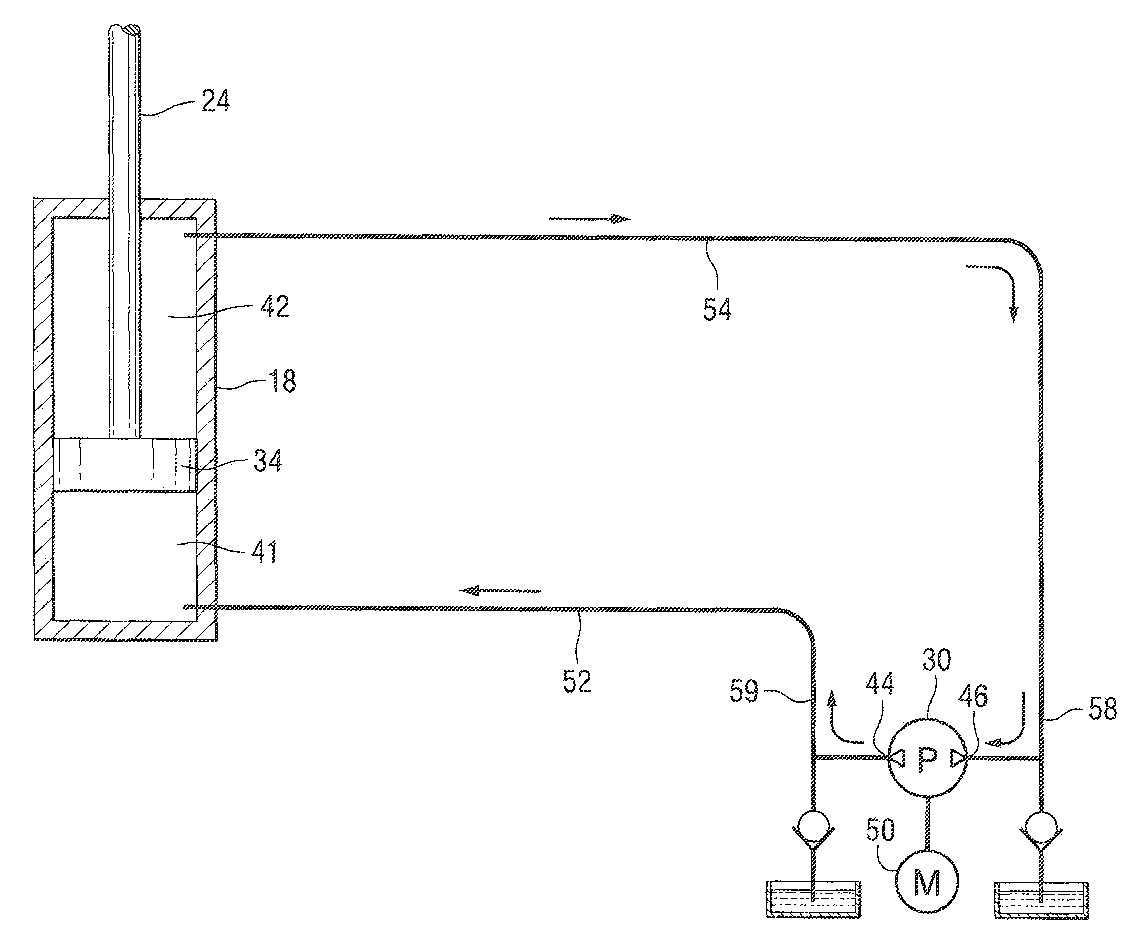
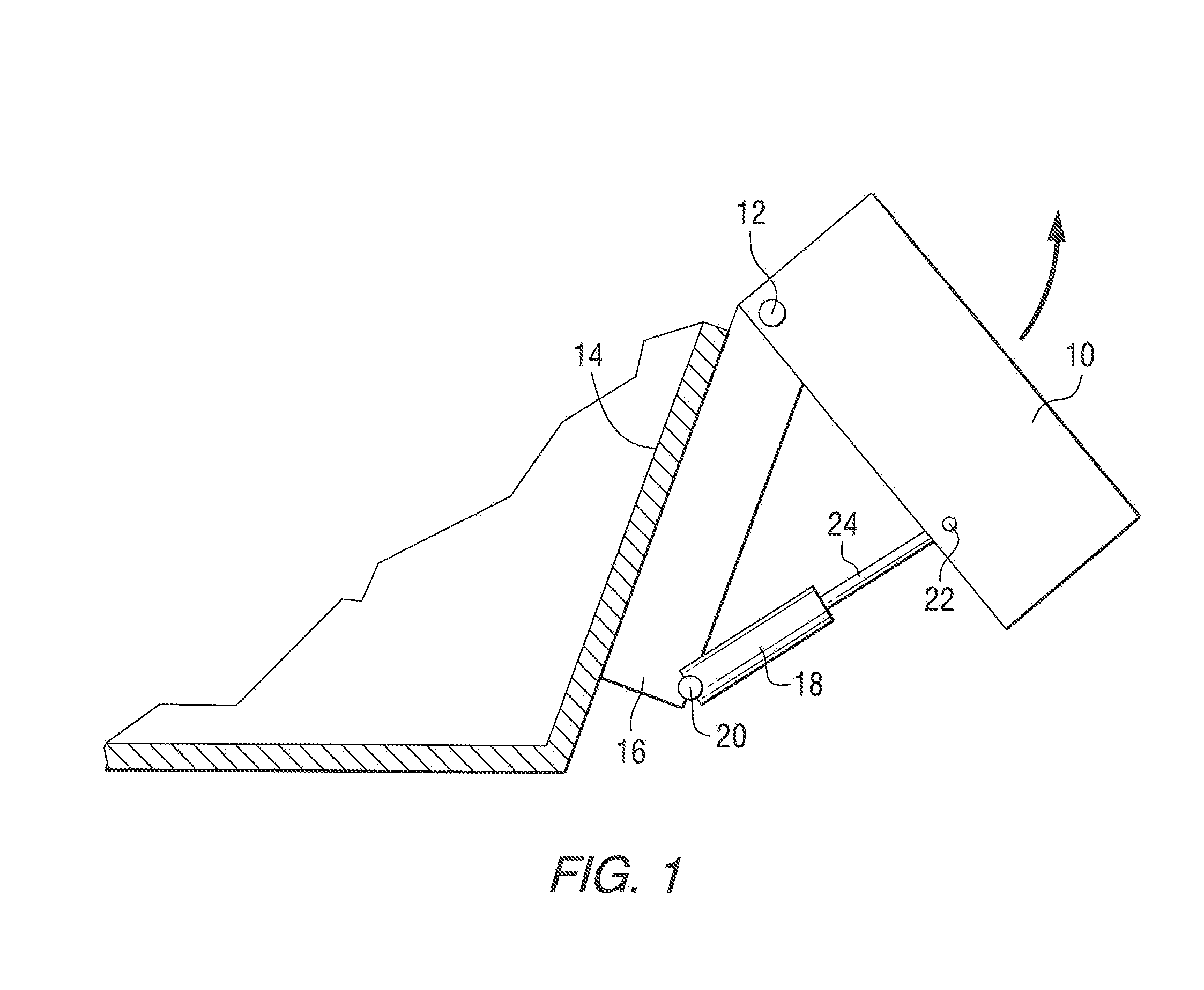
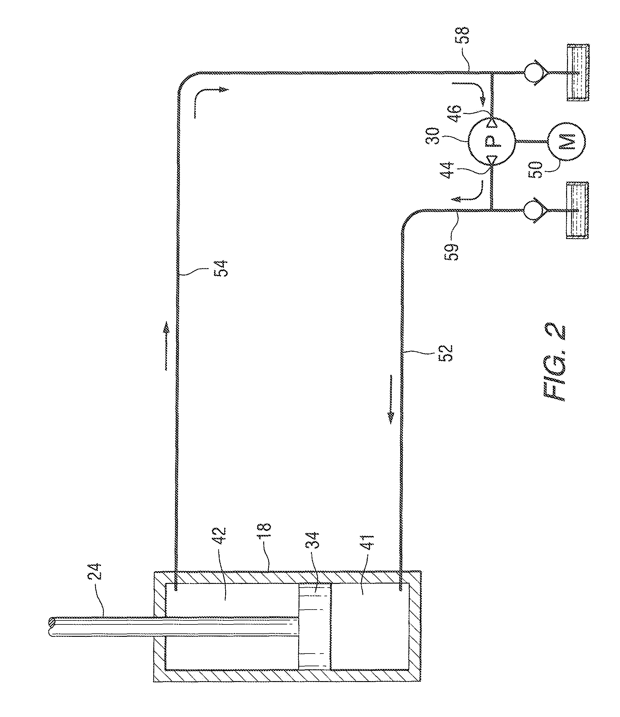
[0031]FIG. 1 is a highly simplified schematic representation of an arrangement which shows how an outboard motor is supported for rotation, about a trim / tilt axis 12, relative to a transom 14 of a marine vessel. Also shown in FIG. 1 is a simplified transom bracket 16 which is schematically shown attached to the transom 14. The transom bracket 16 pivotally supports the outboard motor 10, or an alternative marine propulsion device, and a hydraulic cylinder 18 is connected between a first pivot axis 20 on the transom bracket 16 and a pivot axis 22 on the outboard motor 10. Extension of an actuator shaft 24 from the hydraulic cylinder 18 causes the marine propulsion device 10 to rotate about axis 12, as represented by the arrow in FIG. 1. It should be understood that FIG. 1 is highly schematic and provided simply for the purpose of showing ...


PUM


Abstract

A method is provided for controlling a marine propulsion trim system under two distinct modes of operation. A first mode operates hydraulic cylinders at a slower speed when the associated marine vessel is being operated at a speed above a predetermined threshold. For example, when the marine propulsion device is under load, such as when the marine vessel is operating on plane, the first mode of operation is used and the trim/tilt cylinders are operated at a slower speed. A second mode of operation is used when the marine propulsion system is being operated below a predetermined threshold. In other words, if the marine vessel is operating at a slow speed, the faster mode of operation is used. Similarly, if the marine vessel is being prepared for transport on a trailer, the very slow or non-existent speed of operation of the engine is used as an indicator which causes the second mode of operation to be employed.

Description

BACKGROUND OF THE INVENTION[0001]1. Field of the Invention[0002]The present invention relates generally to a trim system of a marine propulsion device and, more particularly, to a method for causing an actuator of the trim system to move at a selected one of two actuation speeds, depending on conditions.[0003]2. Description of the Related Art[0004]Those skilled in the art of marine propulsion systems are aware of many different types of trim and tilt systems. Typically, trim and / or tilt systems incorporate a hydraulic cylinder connected between the transom of a marine vessel and a marine propulsion device, such as an outboard motor or a sterndrive unit.[0005]U.S. Pat. No. 3,754,394, which issued to Morrison on Aug. 28, 1973, describes a hydraulic control system for an electric lift truck. It includes hydraulically powered mast tilting cylinders and fork hoist cylinders supplied with pressure fluid from an electric motor driven small and large capacity pair of pumps. The hydraulic ci...

Claims


Application Information

Patent Timeline
Patent Type & Authority Patents(United States)
IPC IPC(8): B63H5/125
CPCB63B39/061
Inventor SWAN, ALLEN F.
Owner BRUNSWICK CORPORATION
Why Eureka
Try Eureka