Endoscope and endoscopic system

a technology which is applied in the field of endoscope and endoscope system, can solve the problems of raised production cost, and increased thickness of universal cable, and achieves satisfactory operability

Inactive Publication Date: 2011-05-17
OLYMPUS CORP
View PDF23 Cites 12 Cited by
  • Summary
  • Abstract
  • Description
  • Claims
  • Application Information

AI Technical Summary

Benefits of technology

[0019]The present invention has been made in view of the above-mentioned problems and it is therefore an object to provide an endoscope with which a satisfactory operability can be ensured without decreasing an observation function even when operation parts such as a bending operation switch and an air water switch are provided to an operation section.

Problems solved by technology

Thus, the thickness of the universal cable is increased, and this thick universal cable may disturb the operations.
Thus, problems arise in that extension is difficult and the production cost is raised.
However, a function of supplying a fluid through a duct line, such as an air water process, cannot be realized, so there is a problem of significantly decreasing an observation function, and the like.
According to the example of Japanese Unexamined Patent Application Publication No. 7-124104, the pressure detection is electrically performed, and therefore the above-mentioned illumination light is not effectively used.

Method used


Image

  • Endoscope and endoscopic system
  • Endoscope and endoscopic system
  • Endoscope and endoscopic system

Examples


first embodiment

[0101]Before a specific structure of an endoscopic system according to the present invention is described, a description is first given of a schematic structure of the endoscopic system with reference to FIGS. 1 to 3.

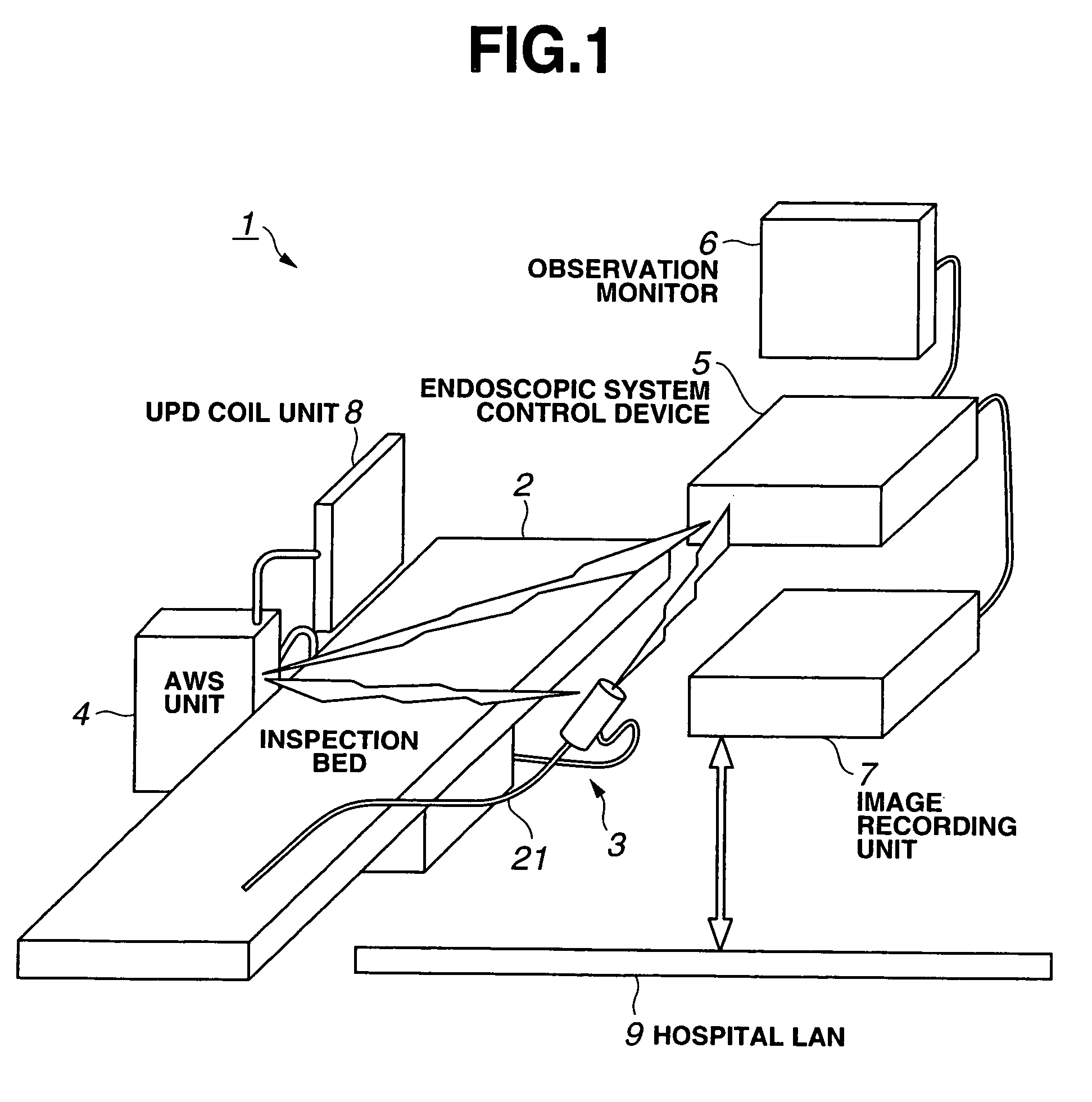
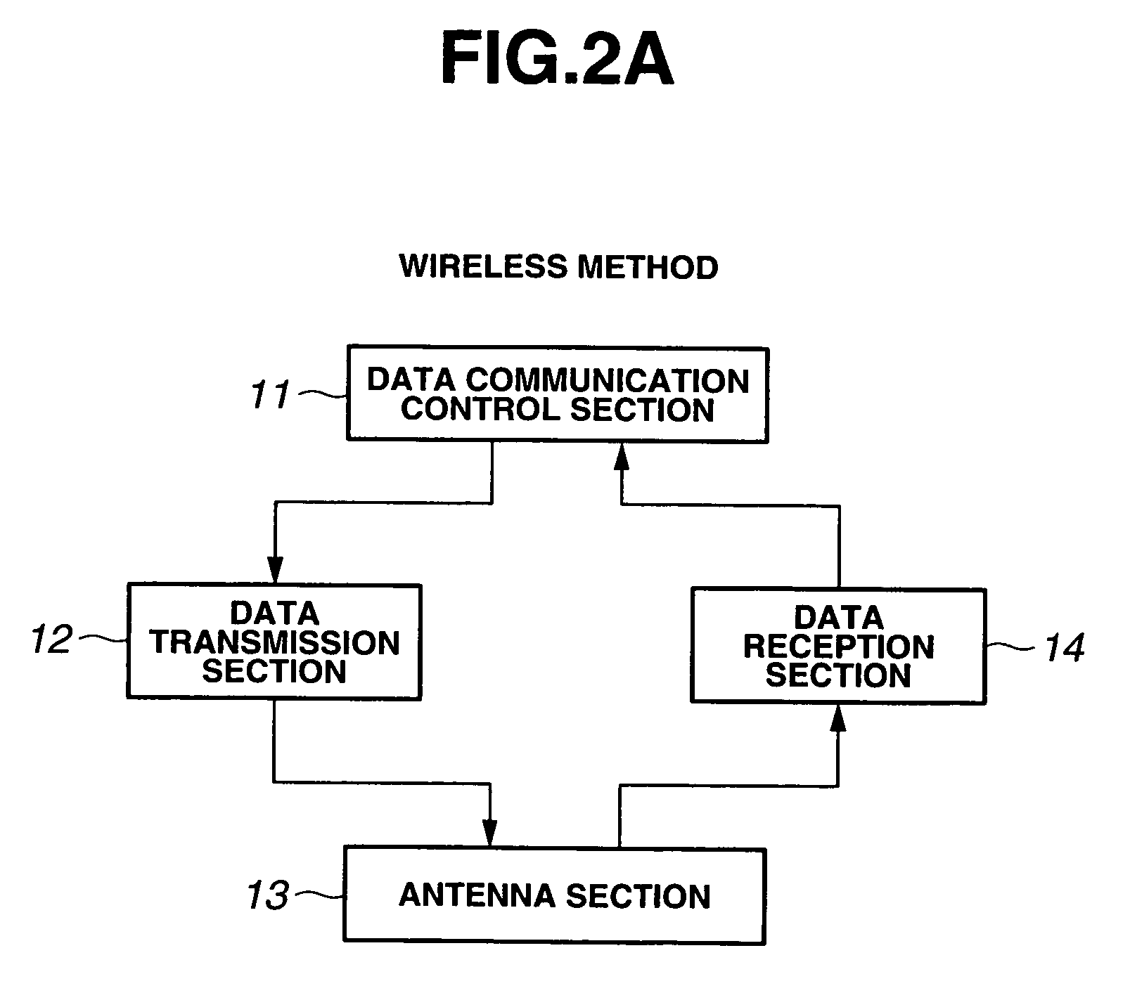
[0102]FIG. 1 shows a schematic structure of an endoscopic system according to the first embodiment of the present invention, FIGS. 2A to 2C are block diagrams showing each example of data communication mode in the endoscopic system according to the first embodiment, and FIG. 3 is an outer appearance perspective view showing a schematic structure of the endoscope in the endoscopic system according to the first embodiment.

[0103]As shown in FIG. 1, an endoscopic system 1 includes a flexible endoscope (also referred to as scope) 3 for performing an endoscopic inspection by inserting the endoscope in a body cavity of a patient (not shown) lying on an inspection bed 2. The endoscopic system 1 includes air water supply / suction unit having functions of airing, watering, and suc...

second embodiment

[0311]Next, the present invention will be described.

[0312]FIG. 27 is a side view with a see-through of a part of internal components of the endoscope in the endoscopic system according to the second embodiment of the present invention. FIGS. 28A and 28B are main part perspective views showing a transparency sensor of the endoscope in the endoscopic system according to the second embodiment. FIG. 29 is a block diagram showing an electric structure of the endoscope in the endoscopic system according to the second embodiment.

[0313]As shown FIG. 27, the endoscope 3B of this embodiment does not have a section corresponding to the signal line 71b of the endoscope 3 in the first embodiment. With an antenna section 141 provided in the operation section 22, the image pickup data by the CCD 25, various data, and the like are wirelessly transmitted and received with the AWS unit 4. That is, in the endoscope of the first embodiment, the signal line 71b functions as the wired common signal trans...

third embodiment

[0337]Next, the present invention will be described.

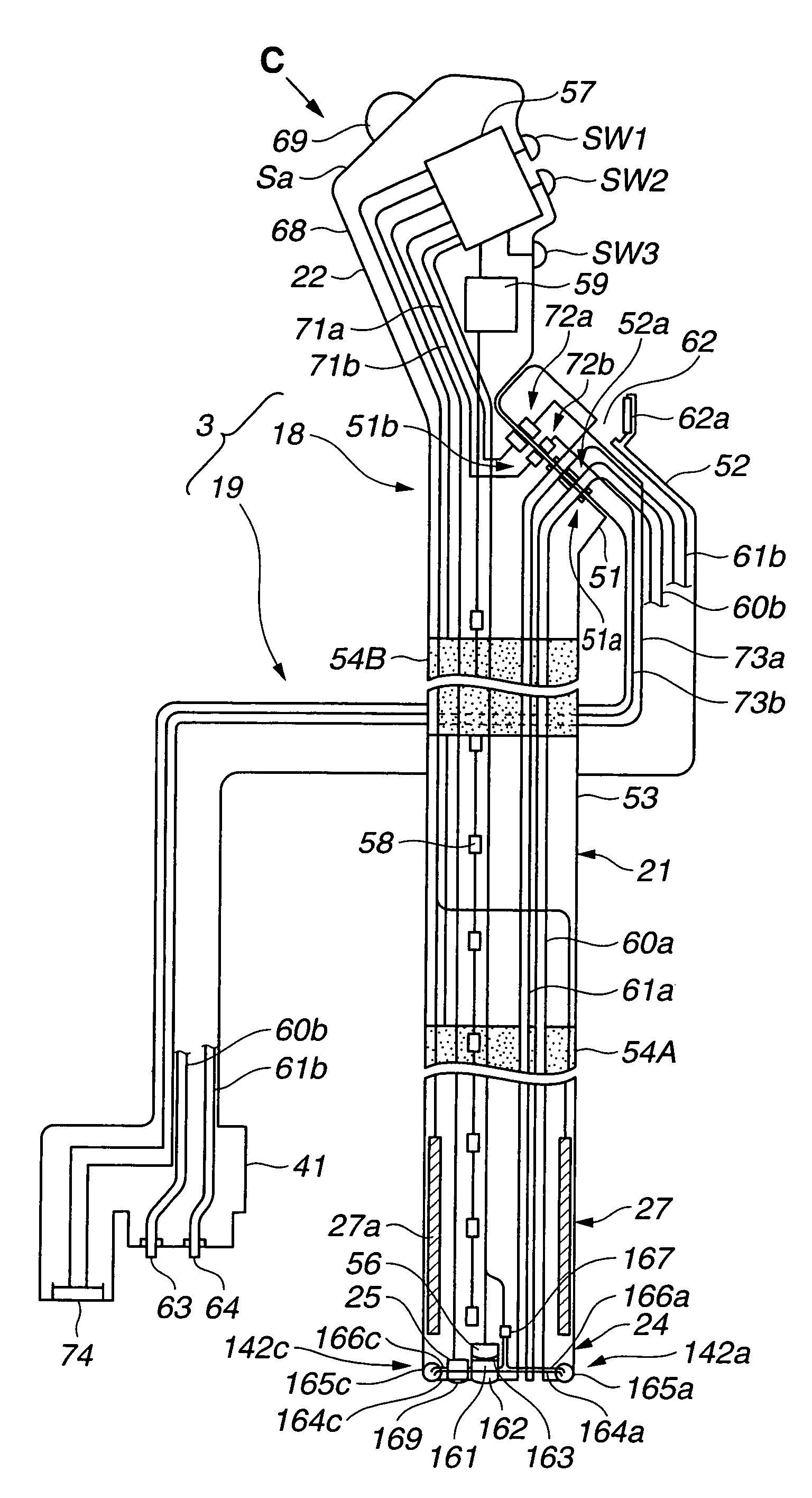
[0338]FIG. 30 is a side view with a see-through of a part of internal components of the endoscope in the endoscopic system according to the third embodiment of the present invention.

[0339]As shown in FIG. 30, the endoscope 3C of the third embodiment does not have the signal line 71b as in the second embodiment, but instead has the antenna section 141 to perform signal data transmission and reception through the antenna section 141. Without the provision of the power supply line 71a, the endoscope 3C further includes a battery 151, a charging circuit 152 connected to the battery, and a noncontact charging coil 153 in the operation section 22.

[0340]The connector section 51 in the operation section 22 of the third embodiment includes the duct line connector section 51a having the air water connector and the suction connector.

[0341]For this reason, the tube unit 19 detachably connected to the endoscope main body 18 of the third embodim...


PUM


Abstract

An endoscope of the present invention includes an insert section inserted in a subject body, an operation section provided at a base end of the insert section, a control process section provided in the operation section, for controlling an image pickup section for capturing a subject body image and a predetermined function in the operation section, a signal circuit extending from the control process section, and a connection section provided to the operation section, for allowing detachable connection of a tube unit through which at least one duct line is inserted.

Description

CROSS REFERENCE TO RELATED APPLICATION[0001]This application is a continuation application of PCT / JP2005 / 003327 filed on Feb. 28, 2005 and claims benefit of Japanese Applications No. 2004-052327 filed in Japan on Feb. 26, 2004, No. 2004-125758 filed in Japan on Apr. 21, 2004, and No. 2004-125759 filed in Japan on Apr. 21, 2004, the entire contents of which are incorporated herein by their reference.BACKGROUND OF THE INVENTION[0002]1. Field of the Invention[0003]The present invention relates to an endoscope to be inserted in a body cavity or the like for performing an endoscopy or the like and an endoscopic system having the endoscope.[0004]2. Description of the Related Art[0005]In recent years, endoscopes having an image pickup element built in an insert section are widely used for an inspection of a body cavity, a therapy with use of an endotherapy product, etc.[0006]As an endoscope having such a built-in image pickup element and a flexible insert section, there is known one includ...

Claims


Application Information

Patent Timeline
Patent Type & Authority Patents(United States)
IPC IPC(8): A61B1/00A61B1/04A61B1/12
CPCA61B1/00039A61B1/042A61B1/00096A61B1/00105A61B1/0005A61B1/00016A61B1/00042
Inventor UCHIMURA, SUMIHIROONODA, FUMIYUKINOGUCHI, TOSHIAKITANIGUCHI, AKIRASUZUKI, KATSUYA
Owner OLYMPUS CORP
Why Eureka
Try Eureka