
Control of a resonant converter
a resonant converter and control technology, applied in the direction of electric variable regulation, process and machine control, instruments, etc., can solve the problems of less control the efficiency of the resonant converter during standby, and the large transient respons
- Summary
- Abstract
- Description
- Claims
- Application Information
AI Technical Summary
Benefits of technology
Problems solved by technology
Method used
Image

Examples
Embodiment Construction
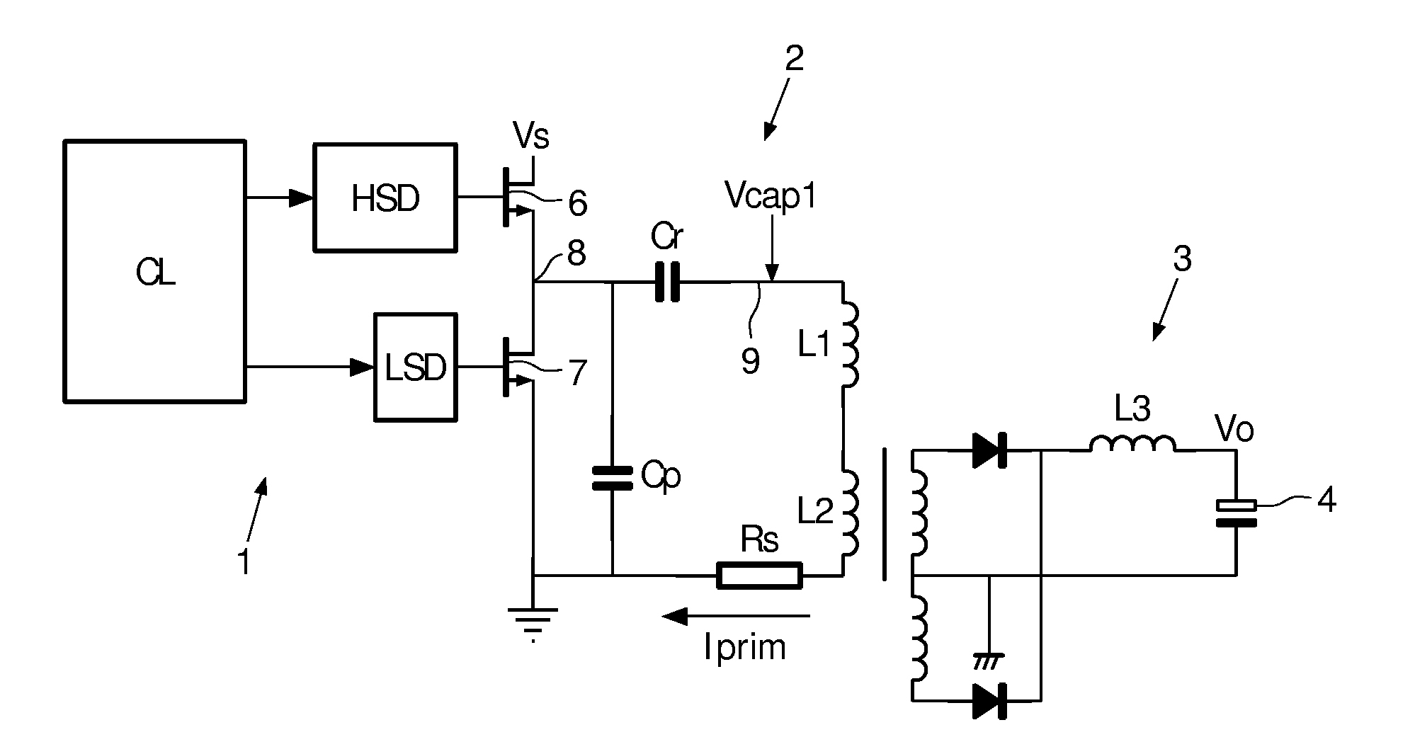
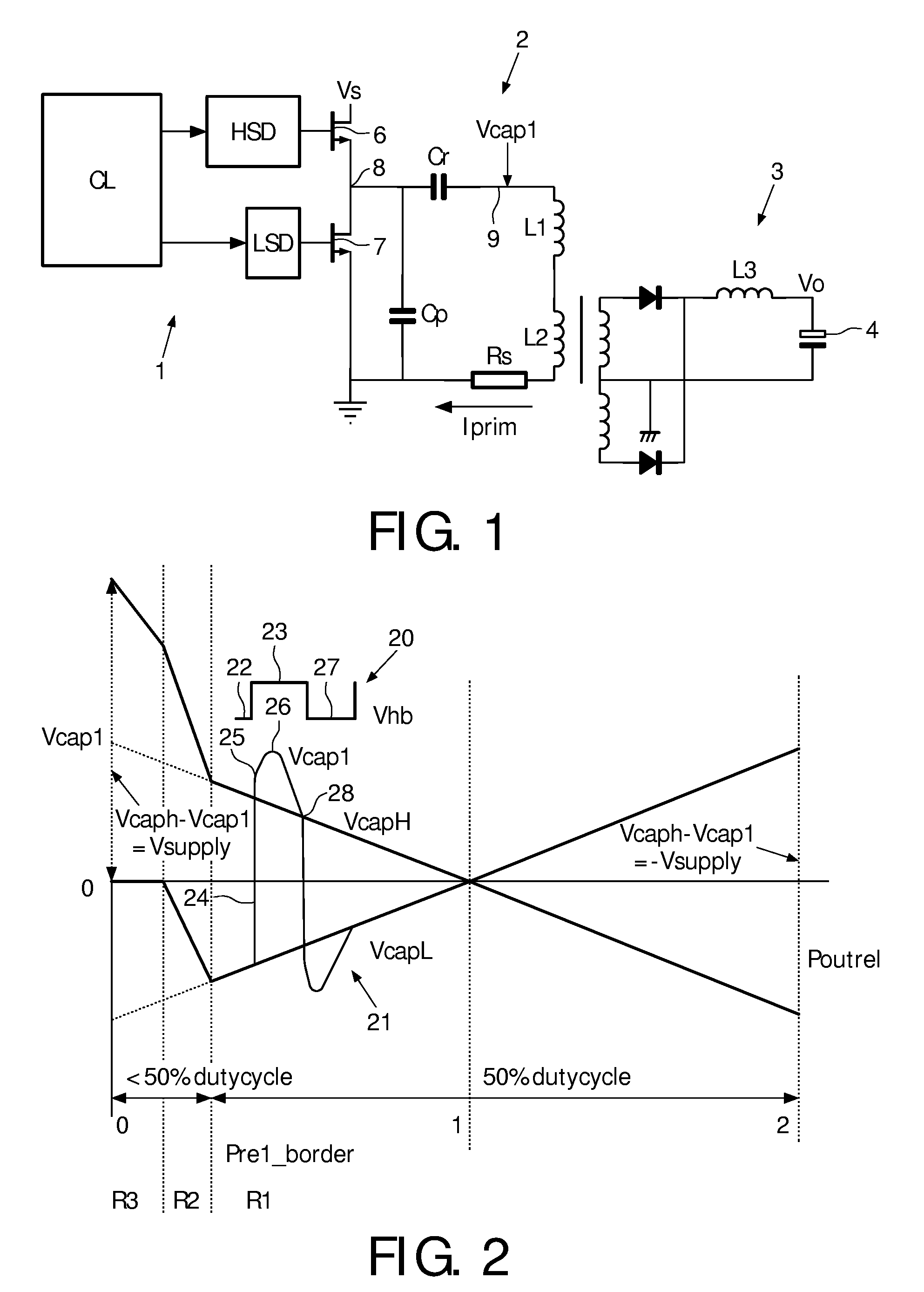
[0031]An embodiment of a resonant converter is illustrated in FIG. 1. The circuit is a resonant LLC converter comprising the resonant capacitor Cr and the inductors L1 and magnetizing inductance L2, components that form part of a resonant circuit or a resonant tank. A transformer and rectifier circuit is used here to create a DC output voltage V0. The output current can be made continuous by adding a series inductance L3. The circuit comprises three parts. A first part 1 is the control part, which comprises a control logic CL for generating control signals for opening and closing the switches 6, 7 by means of drivers HSD and LSD. A second part 2 is the primary circuit, and a third part 3 is the secondary circuit. The resonant converter is connected to a voltage supply Vs so that electrical energy may be supplied a load that e.g. may be connected to the output terminals 4 at the secondary side. The resonant converter comprises first 6 and second 7 series-arranged, controllable switch...
PUM
 Abstract
Description
Claims
Application Information