Control of a resonant converter by setting up criteria for state parameters of the resonant converter

a technology of resonant converter and state parameter, which is applied in the direction of electric variable regulation, process and machine control, instruments, etc., can solve the problems of difficult stability of the converter, non-overlap time bound to a maximum, and switching losses, so as to improve the stability of the system, the effect of reducing the number of turns on losses and fast control

Active Publication Date: 2013-04-16
NXP BV
View PDF17 Cites 4 Cited by
  • Summary
  • Abstract
  • Description
  • Claims
  • Application Information

AI Technical Summary

Benefits of technology

[0007]In one embodiment, the object is achieved by providing improved means to control the converter (e.g. a near capacitive mode resonant converter) so that a simpler, more robust and cheaper resonant converter may be provided. Preferably, the invention alleviates, mitigates or eliminates one or more of the above or other disadvantages singly or in any combination.
[0009]Operating the resonant converter in this manner gives rise to a number of advantages. Operating the switches directly from monitoring the primary current and optionally the capacitor voltage can lead to a faster control and better stability of the system.
[0010]A further advantage is that a soft switch-on of each switch with minimum turn on losses may be obtained, by comparing the primary current and optionally the capacitor voltage in the circuit for each conduction interval with a reference value. The reference value may e.g. be representing a minimum energy for charging the capacitance at the half bridge point to an opposite supply rail. An even further advantage is that it is possible to create a cycle-by-cycle near capacitive mode protection. One of the possible technical effects obtained by a cycle-by-cycle near capacitive mode protection is that no frequency regulation loop is necessary, because the converter is no longer controlled by a frequency. Instead it is controlled cycle-by-cycle. A cycle-by-cycle NCM, Near Capacitive Mode, protection furthermore gives the possible technical effects of instant capacitive mode protection without practical limitation for speed of the main control loop and / or instant capacitive mode protection for duty cycles different from 50% with operation up to the NCM border for the high side switch (HSS) and the low side switch (LSS).
[0011]An important advantage of an embodiment of the present invention compared with the state of art technology is that the necessary action may be taken in advance, preventing the converter from entering into the capacitive mode, also during transients that occur in both the supply voltage or load.
[0012]An even further advantage is that hard switching may be prevented since, HSS or LSS may be turned off at a certain current, while the absolute value of this current is falling to zero after it has first reached its maximum value during the switch conduction interval thereby preventing zero crossing of the current and therefore hard switching.

Problems solved by technology

However, the non-overlap time is bound to a maximum because hard switching also occurs in the case of a too long overlap time so that switching losses occur.
A disadvantage of this method is it may be difficult to stabilize the converter.

Method used


Image

  • Control of a resonant converter by setting up criteria for state parameters of the resonant converter
  • Control of a resonant converter by setting up criteria for state parameters of the resonant converter
  • Control of a resonant converter by setting up criteria for state parameters of the resonant converter

Examples


Embodiment Construction

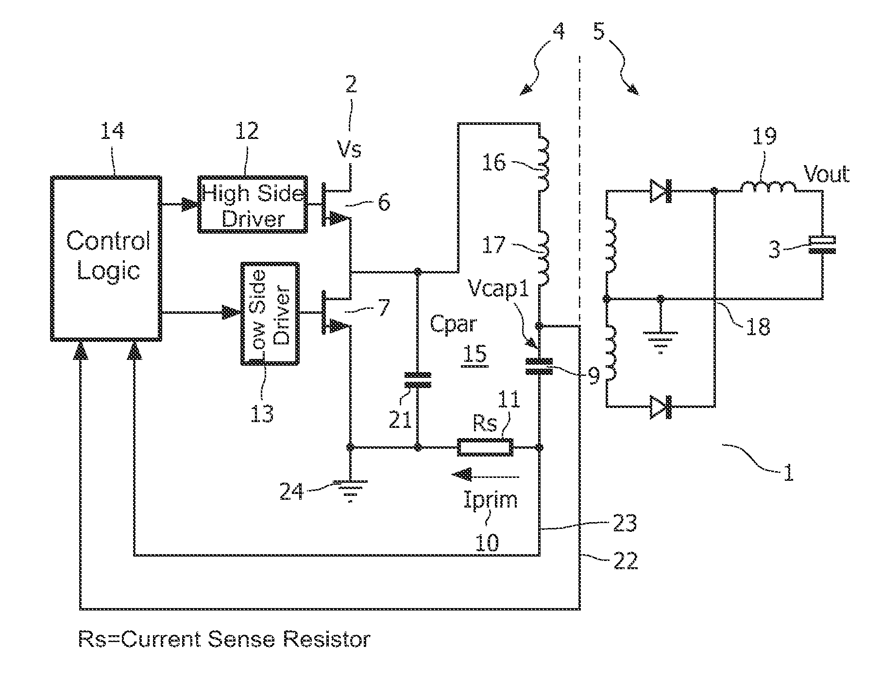
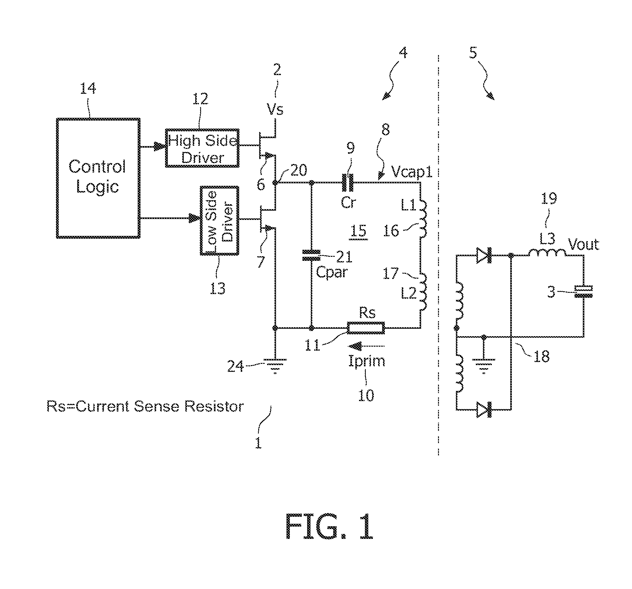
[0021]FIG. 1 illustrates a basic diagram of a resonant LLC converter 1 which is formed as a resonant half-bridge converter. The converter comprises a transformer having a primary side 4 and a secondary side 5. The converter 1 is adapted to supply electric energy from a DC energy supply source, Vs 2 on the primary side of the transformer, to a load (not shown) connected at Vout 3 on the secondary side of the transformer.

[0022]Furthermore, the converter comprises a first and a second controllable switch, here denoted as a High Side (HS) controllable switch 6 and a Low Side (LS) controllable switch 7. The switches are arranged in series with each other. The high side and low side switches may, for example, be a transistor, a thyristor, a MOSFET, etc.

[0023]A resonant capacitor Cr 9 of the LLC converter is having a certain voltage Vcap18 at a point in the circuit. In the resonant tank 15 a current, Iprim 10 is flowing. The voltage Vcap1 is also referred to as the capacitor voltage, the v...


PUM


Abstract

The invention deals with the control of a resonant LLC converter by setting up criteria for state parameters of the resonant converter, so that the converter may be operated in a near capacitive mode. The current flowing in the resonant tank and optionally the voltage at the a predetermined point in the resonant tank are monitored, and wherein a switch (a high side switch or a low side switch) is turned off when a first criterion is fulfilled together with a second criterion or optionally a third criterion, the first criterion ensuring a minimum time has lapsed after the switch is turned on, the second criterion being that the absolute value of the current is reaching a predetermined current level, the third criterion being that the voltage at the predetermined point reaches a predetermined voltage level.

Description

FIELD OF THE INVENTION[0001]The invention relates to control of a resonant converter, and in particular to the control of a near capacitive mode in the resonant converter.BACKGROUND OF THE INVENTION[0002]In order to achieve a satisfactory operation of a resonant converter, it is important that switches for generating an alternating current are switched on and off at the right instant. A frequency at which the switches are operated defines a mode of operation of the converter. If the frequency is sufficiently high, the energy converter operates in a regular inductive mode.[0003]The converter operates in a near-capacitive mode when the switching frequency of the switches, and hence the frequency of the alternating current through the primary side of the transformer is decreased to a point where the alternating current is at least almost in phase with a alternating current at a bridge node.[0004]Generally, it is desirable that the energy converter operates in the inductive mode. To thi...

Claims


Application Information

Patent Timeline
Patent Type & Authority Patents(United States)
IPC IPC(8): H02M3/335
CPCH02M3/3376Y02B70/1433Y02B70/10
Inventor HALBERSTADT, HANS
Owner NXP BV
Why Eureka
Try Eureka