Control of a resonant converter

a resonant converter and control technology, applied in the direction of electric variable regulation, process and machine control, instruments, etc., can solve the problems of difficult stability of the converter, non-overlap time bound to a maximum, switching loss, etc., to achieve the effect of reducing the number of turns on losses, improving the stability of the system, and fast control

Active Publication Date: 2010-02-11
NXP BV
View PDF15 Cites 22 Cited by
  • Summary
  • Abstract
  • Description
  • Claims
  • Application Information

AI Technical Summary

Benefits of technology

[0009]Operating the resonant converter in this manner gives rise to a number of advantages. Operating the switches directly from monitoring the primary current and optionally the capacitor voltage can lead to a faster control and better stability of the system.
[0010]A further advantage is that a soft switch-on of each switch with minimum turn on losses may be obtained, by comparing the primary current and optionally the capacitor voltage in the circuit for each conduction interval with a reference value. The reference value may e.g. be representing a minimum energy for charging the capacitance at the half bridge point to an opposite supply rail. An even further advantage is that it is possible to create a cycle-by-cycle near capacitive mode protection. One of the possible technical effects obtained by a cycle-by-cycle near capacitive mode protection is that no frequency regulation loop is necessary, because the converter is no longer controlled by a frequency. Instead it is controlled cycle-by-cycle. A cy...

Problems solved by technology

However, the non-overlap time is bound to a maximum because hard switching also occurs in the case of a too long ov...

Method used


Image

  • Control of a resonant converter
  • Control of a resonant converter
  • Control of a resonant converter

Examples


Embodiment Construction

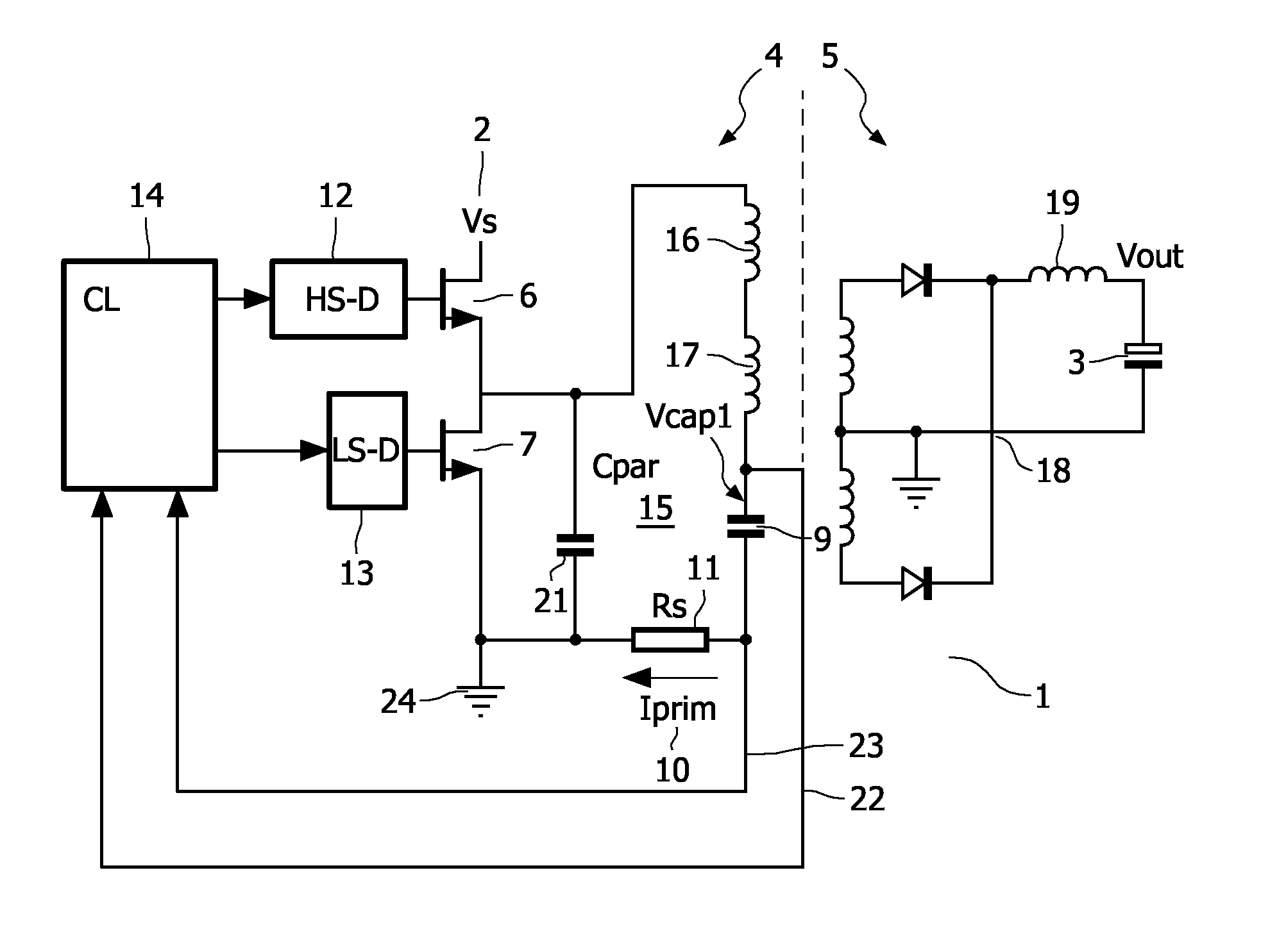
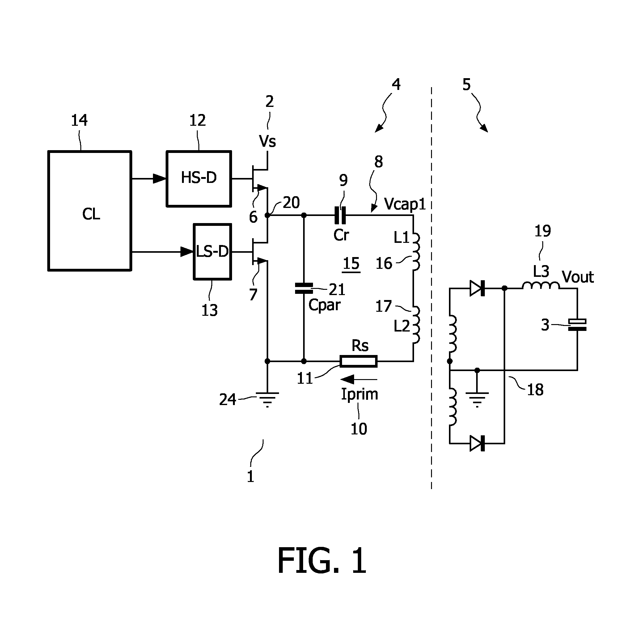
[0021]FIG. 1 illustrates a basic diagram of a resonant LLC converter 1 which is formed as a resonant half-bridge converter. The converter comprises a transformer having a primary side 4 and a secondary side 5. The converter 1 is adapted to supply electric energy from a DC energy supply source, Vs 2 on the primary side of the transformer, to a load (not shown) connected at Vout 3 on the secondary side of the transformer.

[0022]Furthermore, the converter comprises a first and a second controllable switch, here denoted as a High Side (HS) controllable switch 6 and a Low Side (LS) controllable switch 7. The switches are arranged in series with each other. The high side and low side switches may, for example, be a transistor, a thyristor, a MOSFET, etc.

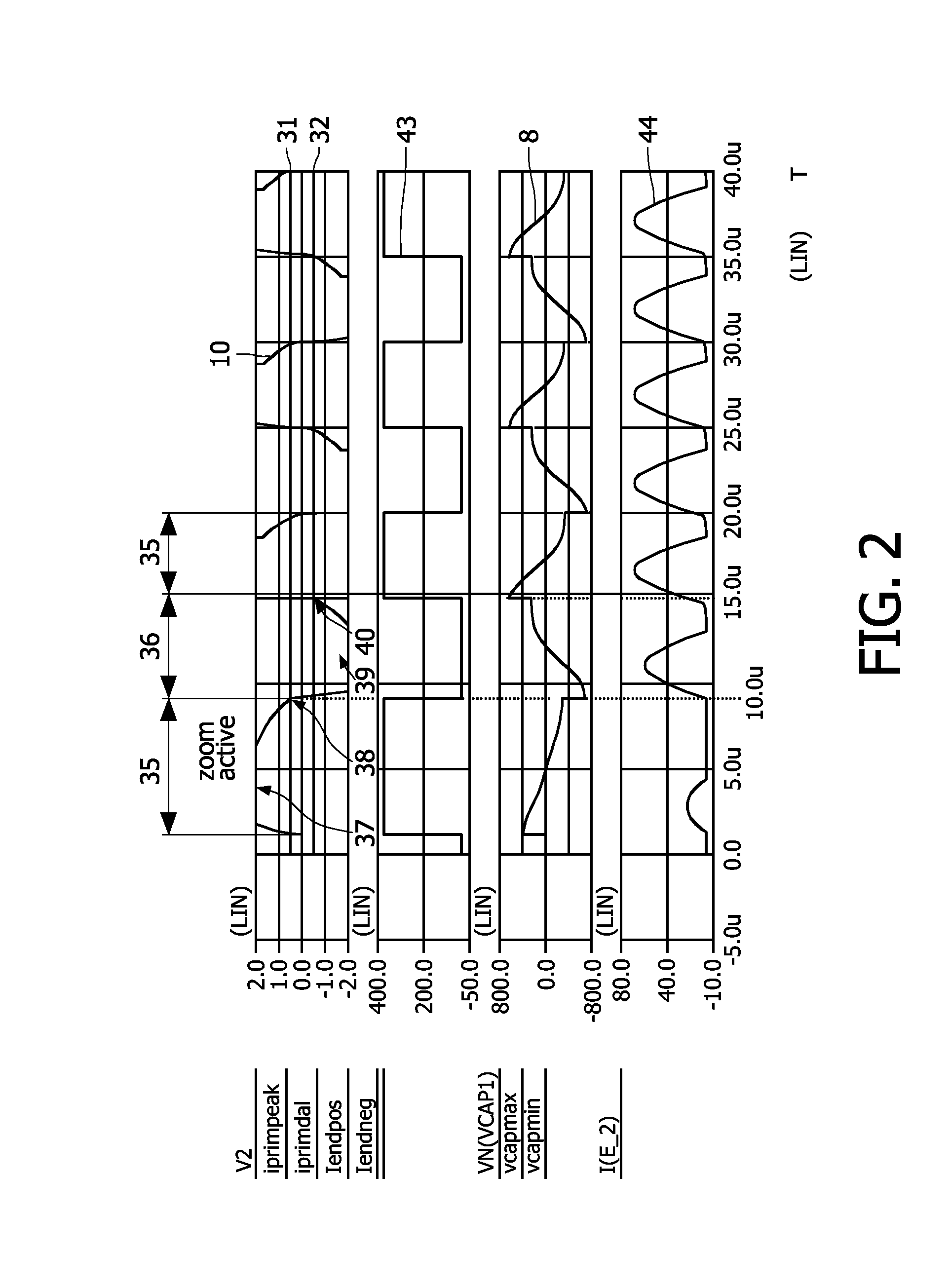
[0023]A resonant capacitor Cr 9 of the LLC converter is having a certain voltage Vcap18 at a point in the circuit. In the resonant tank 15 a current, Iprim 10 is flowing. The voltage Vcap1 is also referred to as the capacitor voltage, the v...


PUM


Abstract

The invention deals with the control of a resonant LLC converter by setting up criteria for state parameters of the resonant converter, so that the converter may be operated in a near capacitive mode. The current flowing in the resonant tank and optionally the voltage at the a predetermined point in the resonant tank are monitored, and wherein a switch (a high side switch or a low side switch) is turned off when a first criterion is fulfilled together with a second criterion or optionally a third criterion, the first criterion ensuring a minimum time has lapsed after the switch is turned on, the second criterion being that the absolute value of the current is reaching a predetermined current level, the third criterion being that the voltage at the predetermined point reaches a predetermined voltage level.

Description

FIELD OF THE INVENTION[0001]The invention relates to control of a resonant converter, and in particular to the control of a near capacitive mode in the resonant converter.BACKGROUND OF THE INVENTION[0002]In order to achieve a satisfactory operation of a resonant converter, it is important that switches for generating an alternating current are switched on and off at the right instant. A frequency at which the switches are operated defines a mode of operation of the converter. If the frequency is sufficiently high, the energy converter operates in a regular inductive mode.[0003]The converter operates in a near-capacitive mode when the switching frequency of the switches, and hence the frequency of the alternating current through the primary side of the transformer is decreased to a point where the alternating current is at least almost in phase with a alternating current at a bridge node.[0004]Generally, it is desirable that the energy converter operates in the inductive mode. To thi...

Claims


Application Information

Patent Timeline
IPC IPC(8): H02M3/335
CPCY02B70/1433H02M3/3376Y02B70/10
Inventor HALBERSTADT, HANS
Owner NXP BV
Why Eureka
Try Eureka