Control of a Resonant Converter

a resonant converter and control loop technology, applied in the direction of electric variable regulation, process and machine control, instruments, etc., can solve the problems of less control loop stability, less control loop efficiency, and large transient respons

Active Publication Date: 2008-10-30
NXP BV
View PDF10 Cites 37 Cited by
  • Summary
  • Abstract
  • Description
  • Claims
  • Application Information

AI Technical Summary

Benefits of technology

[0011]An embodiment of the present invention provides improved means to control the converter so that a simpler, more robust and cheaper resonant converter may be provided. Preferably, the invention alleviates, mitigates or eliminates one or more of the above or other disadvantages singly or in any combination.
[0013]Operating the resonant converter in this manner gives rise to a number of advantages. By operating the switches directly from monitoring the primary current and the voltage at a predetermined point, a faster control and better stability of the system can be provided. Furthermore, from the setting of the criteria and / or the setting of the control parameters, one may directly include safety features, such as shorted output protection. Even further, a smooth combination of high output power at 50% duty cycle may be combined with high efficient low output power / standby mode, by setting up criteria where different criteria are taking different aspects into account, and even allows operating at duty cycles different from 50% if desired. An even further advantage is that a symmetrically controlled converter can be obtained if necessary. It should be noted that the scope of this patent also covers an embodiment in which the predetermined voltage is replaced by an indirect measurement as explained hereinafter in connection with FIG. 7.

Problems solved by technology

This history gives rise to rather large transient responses and more complicated stability issues of the control loop, especially if the converter operates close to resonance.
For modern designs, efficiency at low load and input power during standby (no output power taken) have become a major issue.
With the traditional 50% duty cycle control this issue is difficult to solve, because of the large circulating energy at low load.
A solution for this is burst mode, but burst mode is not always allowed, because of the large ripple at the output.
Also sudden changeover from normal mode to burst mode or back can give intolerable transients at the output.
Varying the duty cycle at a fixed frequency can however give intolerable change in sign of the loop gain.

Method used


Image

  • Control of a Resonant Converter
  • Control of a Resonant Converter
  • Control of a Resonant Converter

Examples


Embodiment Construction

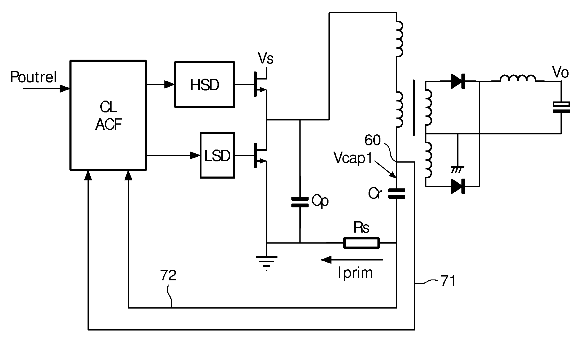
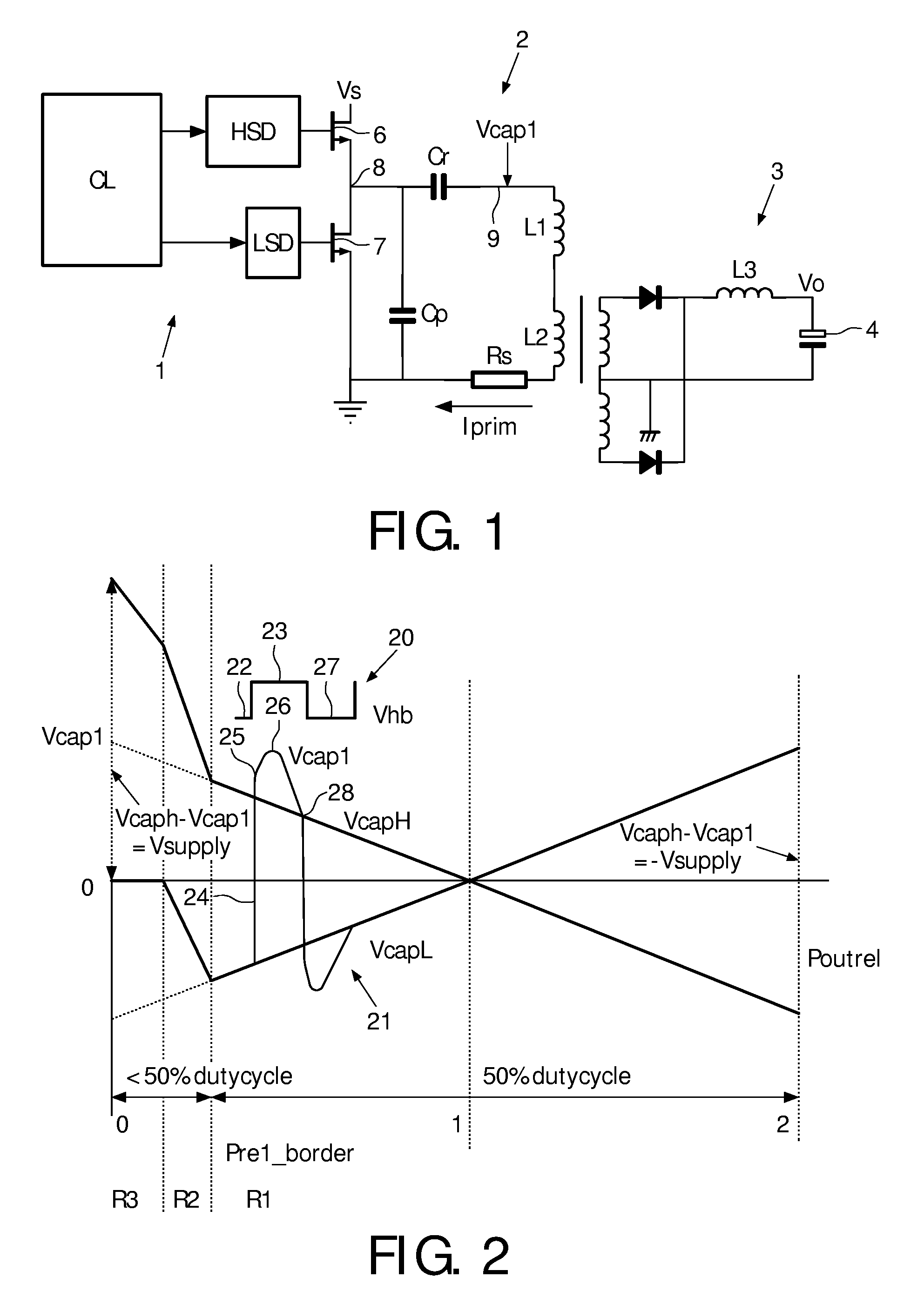
[0031]An embodiment of a resonant converter is illustrated in FIG. 1. The circuit is a resonant LLC converter comprising the resonant capacitor Cr and the inductors L1 and magnetizing inductance L2, components that form part of a resonant circuit or a resonant tank. A transformer and rectifier circuit is used here to create a DC output voltage V0. The output current can be made continuous by adding a series inductance L3. The circuit comprises three parts. A first part 1 is the control part, which comprises a control logic CL for generating control signals for opening and closing the switches 6, 7 by means of drivers HSD and LSD. A second part 2 is the primary circuit, and a third part 3 is the secondary circuit. The resonant converter is connected to a voltage supply Vs so that electrical energy may be supplied a load that e.g. may be connected to the output terminals 4 at the secondary side. The resonant converter comprises first 6 and second 7 series-arranged, controllable switch...


PUM


Abstract

The invention deals with the control of a resonant LLC converter by use of control parameters. The primary current flowing in the resonant tank and a voltage at a predetermined point in the resonant tank are monitored and control parameters are set for a high side conduction interval and control parameters are set for a low side conduction interval, the control parameters for the two conduction intervals being: a peak current of the interval and a predetermined voltage of the interval. The resonant converter comprises series-arranged controllable switches to be connected to the supply source. The resonant converter is operated by setting up criteria for turning off a switch in accordance with criteria including the four control parameters.

Description

FIELD OF THE INVENTION[0001]The invention relates to control of a resonant converter, and in particular to control of the resonant converter by use of control parameters.BACKGROUND OF THE INVENTION[0002]In a state of the art resonant LLC converter, a resonant capacitor and two inductors form a resonant circuit, possible in connection with additional components. The converter further includes a transformer and rectifier circuit that is used to create a DC output voltage. The output current can be made continuous by adding a series inductance in the rectifier circuit. A lot of variations exist for this type of converter, including rectification with a bridge rectifier or no rectification at all as used in a lighting application. Also the transformer can be left out in some cases.[0003]In order to achieve satisfactory operation of a resonant converter, it is important that the switches for generating an alternating current are switched on and off at the right instant. A frequency at wh...

Claims


Application Information

Patent Timeline
Patent Type & Authority Applications(United States)
IPC IPC(8): H02M3/337
CPCH02M3/3376Y02B70/1433H02M2001/0058Y02B70/1491H02M1/0058Y02B70/10
Inventor HALBERSTADT, HANS
Owner NXP BV
Why Eureka
Try Eureka