
Dust cap for fiber optic adapter

a fiber optic adapter and dust cap technology, applied in the field of dust caps, can solve the problems of eye damage, damage or degrade a signal, failure to provide proper long-term engagement, etc., and achieve the effect of preventing dust contamination

Inactive Publication Date: 2011-05-17
CORNING OPTICAL COMM LLC
View PDF24 Cites 10 Cited by
  • Summary
  • Abstract
  • Description
  • Claims
  • Application Information

AI Technical Summary

Benefits of technology

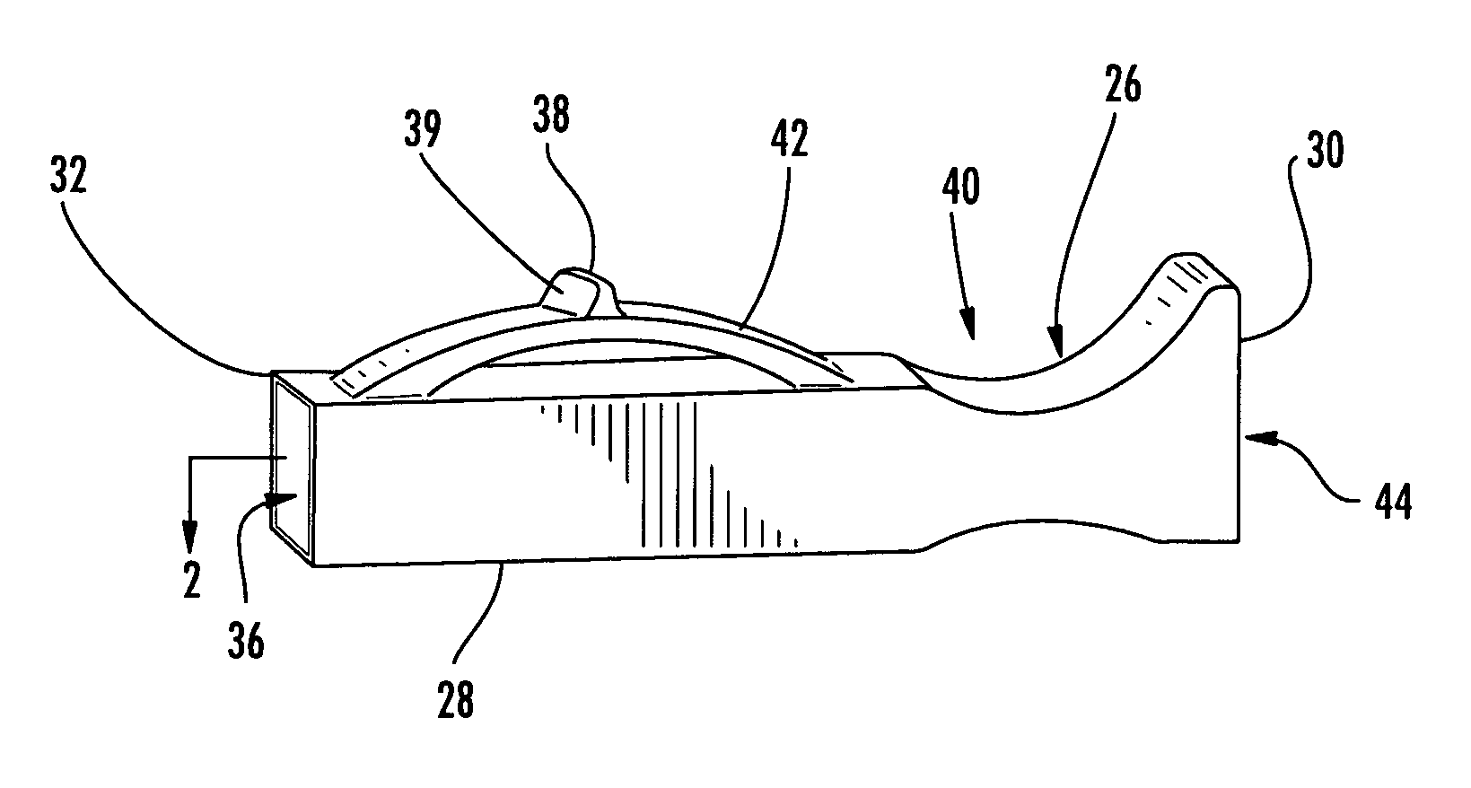
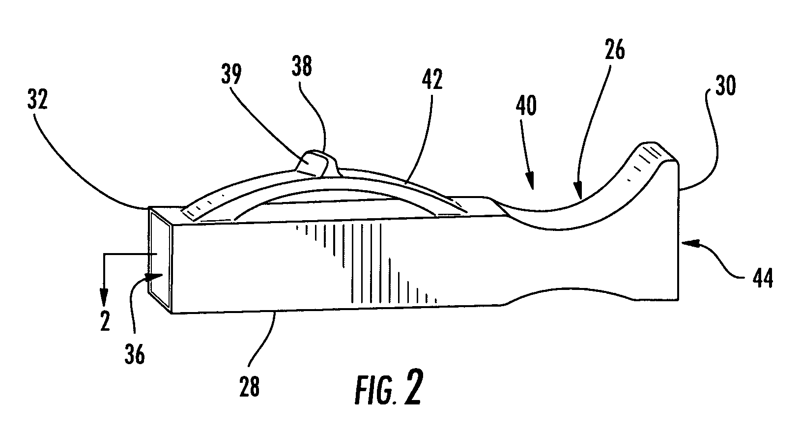
The present invention provides an adapter dust cap that can securely engage the internal geometry of an adapter and prevent dust contamination. The dust cap is translucent and can visually indicate the presence of light emanating from a connector engaged with the back side of the adapter. The dust cap can be easily installed and removed, and it has a spring and keying structure that securely engages the adapter and prevents dislodgement from vibration or thermal forces. The invention also provides a dual configuration for a duplex adapter dust cap that can securely engage the inner structural geometry of the adapter. The technical effects of the invention include improved protection of adapters from dust and other contaminants, and improved visual indication of light emanating from connectors.

Problems solved by technology

In the case of invisible light being transmitted through the back side connector, the visible light requires detection through the use of costly detection equipment only after the dust cap has been removed from the adapter.
When removing a dust cap to detect the invisible light, the opportunity exists for eye damage if the light is accidentally viewed.
Further, removing the back side connector from its adapter or removing the dust cap from the front side of the adapter also introduces an opportunity for dust and other contamination to reach the polished end face of the back side connector that may damage or degrade a signal.
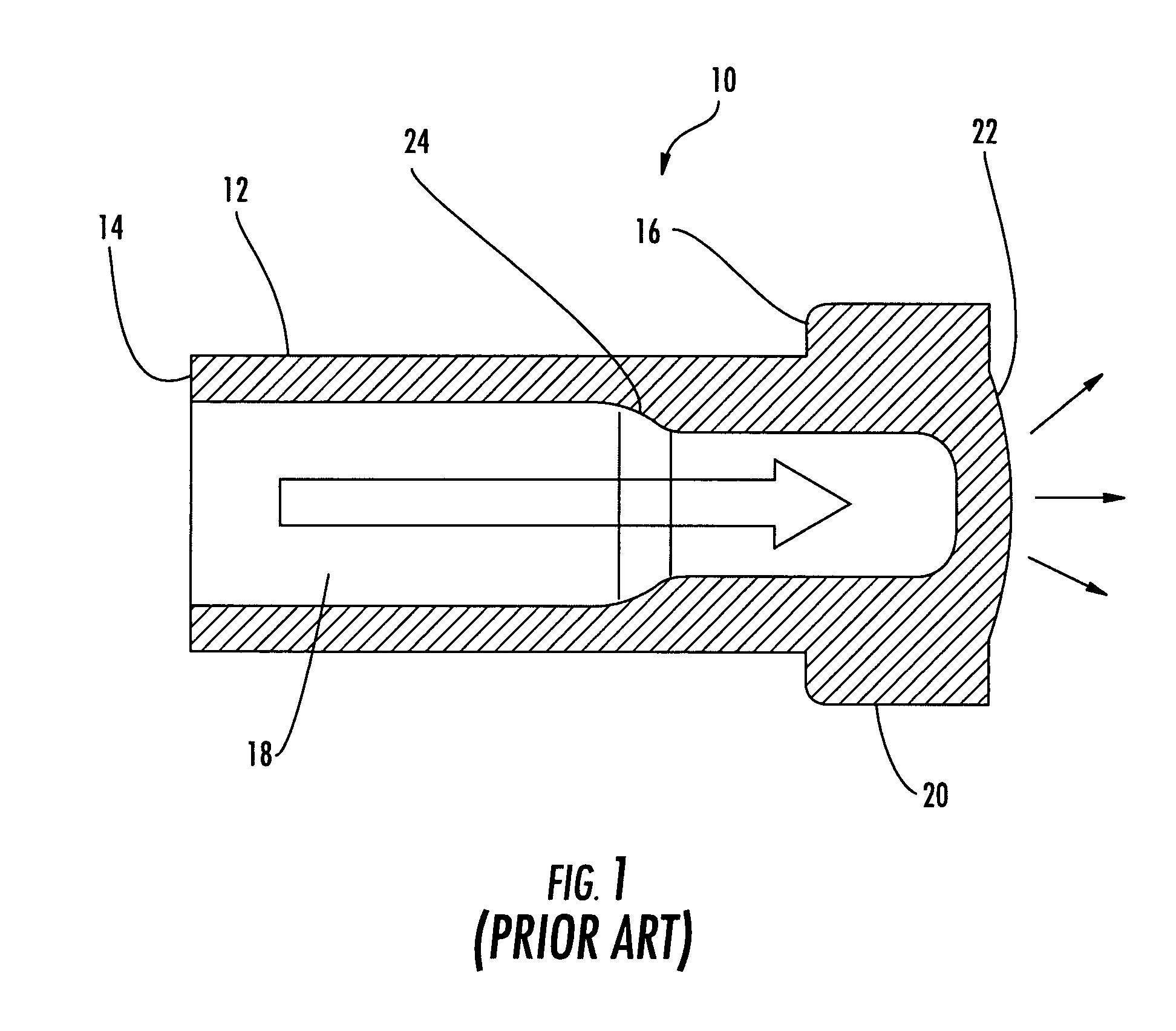
Dust caps have also been designed to engage adapters by interference fit, and have not included structure to engage with the adapter in the manner that a connector does, thus conventional dust caps have failed to provide proper long-term engagement, and as a result, commonly disengage from their adapter and fall to the floor.
While conventional dust caps are suitable for detecting visible light through the dust cap, by design they are not capable of detecting invisible light through themselves, and are not properly designed to remain engaged for long periods of time without becoming dislodged.
Disadvantageously, a long term interference fit requires tight molding tolerances of both the dust caps and the adapters.
Further, conventional dust caps are subject to thermal expansion and other external forces such as vibration which may cause the dust cap to dislodge from the adapter.

Method used


Image

  • Dust cap for fiber optic adapter
  • Dust cap for fiber optic adapter
  • Dust cap for fiber optic adapter

Examples


Embodiment Construction

The present invention will now be described more fully hereinafter with reference to the accompanying drawings in which exemplary embodiments of the invention are shown. However, this invention may be embodied in many different forms and should not be construed as limited to the embodiments set forth herein. These exemplary embodiments are provided so that this disclosure will be both thorough and complete, and will fully convey the scope of the invention to those skilled in the art. Like reference numbers refer to like elements throughout the various drawings. Specific embodiments of translucent adapter dust caps operable for securely engaging the inner structural geometry of a fiber optic connector adapter and for producing a visual signal notification of visible or invisible light emanating from a connector inserted into the adapter are shown throughout the figures. It should be understood, however, that alternative adapter dust cap designs may vary in order to accommodate variou...


PUM


Abstract

An adapter dust cap comprising a dust cap body defining a clearance extending at least partially therethrough, a resilient member attached to the connector body, and a latching feature attached to the resilient member and configured to engage within internal geometry defined by a connector adapter. The adapter dust cap is translucent so that visible light from a connector may diffuse therethrough, and may include a material or coating thereon for converting light in the invisible spectrum to visible light so that the light can be detected through the dust cap without removing the dust cap from an adapter to which it is engaged.

Description

BACKGROUND OF THE INVENTION1. Field of the InventionThe present invention relates generally to dust caps that engage with fiber optic connector adapters and, more particularly, to dust caps that have a structure operable for securely engaging the internal geometry of a fiber optic connector adapter, and optionally including material that reacts with invisible light emanating from a connector engaged with the back side of the adapter to produce a visual signal.2. Technical BackgroundFiber optic applications using optical connectors and adapters frequently include requirements for the identification of specific optical fibers during installation, interconnection and maintenance testing. Examples of such applications include multi-dwelling units, cabinets, local area networks and industrial networks, among others. Within these systems, connections between optical fibers are typically accomplished through the use of adapters mounted within patch panels, cabinets or racks. A patch panel ...

Claims


Application Information

Patent Timeline
Patent Type & Authority Patents(United States)
IPC IPC(8): G02B6/36
CPCG02B6/3849G02B6/3825
Inventor PARKMAN, III, LOUIS EDWARDMUDD, RONALD LEEJONG, MICHAEL DE
Owner CORNING OPTICAL COMM LLC
Learn More