
Spot weld failure determination method in a finite element analysis

a finite element analysis and failure determination technology, applied in the direction of material strength using steady bending force, manufacturing tools, instruments, etc., can solve the problems of spot weld failure, insufficient welds using beam elements, and insufficient fea models

Active Publication Date: 2011-05-17
ANSYS
View PDF17 Cites 7 Cited by
  • Summary
  • Abstract
  • Description
  • Claims
  • Application Information

AI Technical Summary

Benefits of technology

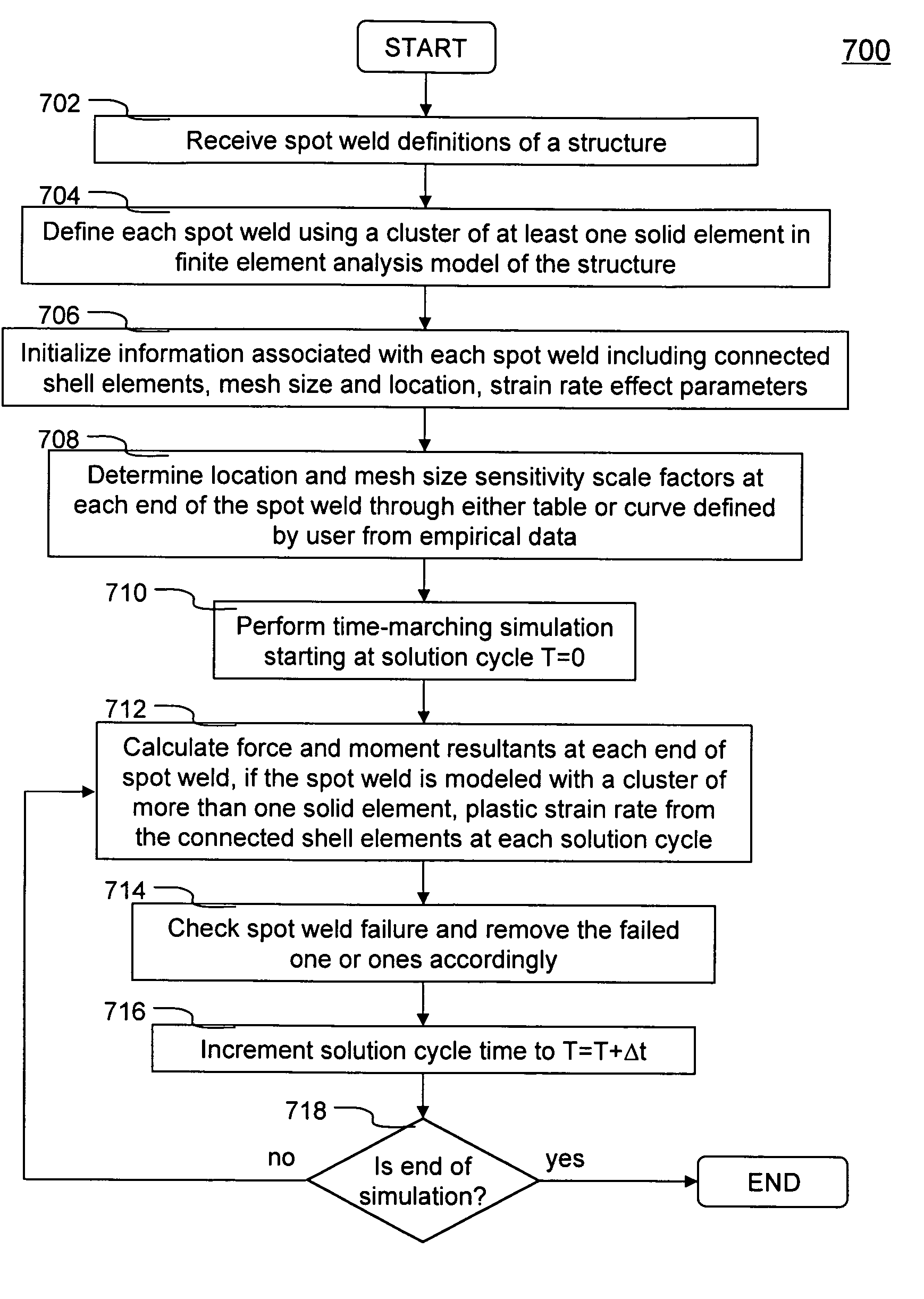
The present invention is a system, method, and software product for determining spot weld failure in a finite element analysis of a structure, such as an automobile. The invention uses a cluster of at least one solid element to represent each spot weld and the parts connected by it. The invention calculates shear and axial stresses acting on the spot weld and checks if the failure criterion is met. The invention also takes into account the sensitivity of the structure to the location and size of the spot weld. The overall plastic strain rate is also calculated and used for checking the spot weld failure. The invention can be used in designing structures to prevent spot weld failure.

Problems solved by technology

A problem associated with crashworthiness simulation is to properly simulate spot welds used for connecting two parts (e.g., sheet metal) in a structure.
This prior art approach required much work in creating the FEA model due to the effort to properly locate nodal points precisely at the weld locations.
Representing spot welds using beam elements are not adequate any more, instead solid elements are used.
Furthermore, in a car crashworthiness simulation, spot weld failure needs to be considered and determined.
However, this method is inconsistent with traditional material failure method used in solid elements.

Method used


Image

  • Spot weld failure determination method in a finite element analysis
  • Spot weld failure determination method in a finite element analysis
  • Spot weld failure determination method in a finite element analysis

Examples


Embodiment Construction

[0031]In the following description, numerous specific details are set forth in order to provide a thorough understanding of the present invention. However, it will become obvious to those skilled in the art that the present invention may be practiced without these specific details. The descriptions and representations herein are the common means used by those experienced or skilled in the art to most effectively convey the substance of their work to others skilled in the art. In other instances, well-known methods, procedures, components, and circuitry have not been described in detail to avoid unnecessarily obscuring aspects of the present invention.

[0032]Reference herein to “one embodiment” or “an embodiment” means that a particular feature, structure, or characteristic described in connection with the embodiment can be included in at least one embodiment of the invention. The appearances of the phrase “in one embodiment” in various places in the specification are not necessarily ...


PUM

PropertyMeasurementUnit
diameteraaaaaaaaaa
diameteraaaaaaaaaa
lengthaaaaaaaaaa

Abstract

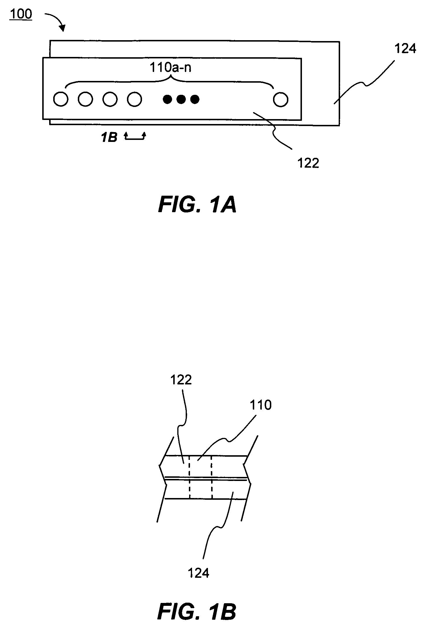
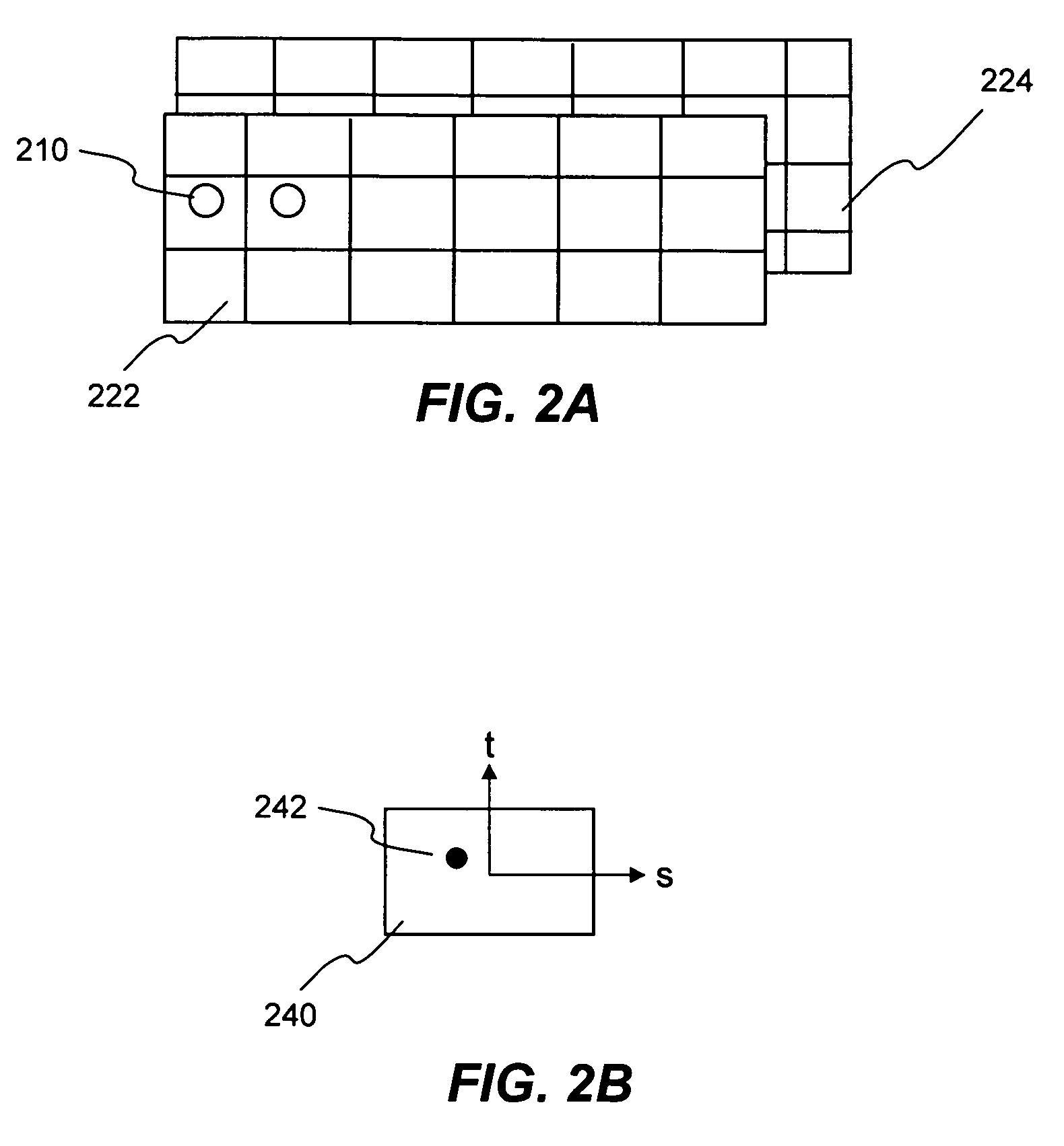
Each spot weld in a structure is represented by a cluster of at least one solid element in a finite element analysis model of the structure. Each spot weld is used for tying together two parts. Each of the two parts are generally represented or modeled as a number of two-dimension shell elements. Since the tie-connection between the spot weld and the two parts can be located arbitrarily within the respective part, the shell elements representing the two parts do not have to be aligned in space. The only requirement is the two shell elements must be overlapped each other such that the spot weld can tie the two shell elements (i.e., one from each part) together. A spot weld failure criterion used for determining failure including shear and axial stresses acted on the spot weld, shell element size and spot weld location sensitivity scale factors and strain rate effect.

Description

FIELD OF THE INVENTION[0001]The present invention generally relates to computer-aided engineering analysis of a structure (e.g., car, airplane), more particularly to a spot weld failure determination method in a finite element analysis.BACKGROUND OF THE INVENTION[0002]Finite element analysis (FEA) is a computer implemented method widely used in industry to model and solve engineering problems relating to complex systems such as three-dimensional non-linear structural design and analysis. FEA derives its name from the manner in which the geometry of the object under consideration is specified. With the advent of the modem digital computer, FEA has been implemented as FEA software. Basically, the FEA software is provided with a model of the geometric description and the associated material properties at each point within the model. In this model, the geometry of the system under analysis is represented by solids, shells and beams of various sizes, which are called elements. The vertic...

Claims


Application Information

Patent Timeline
Patent Type & Authority Patents(United States)
IPC IPC(8): G06G7/48B23K9/28A47J36/02G01N3/20
CPCB23K11/34G01N3/00B23K31/12G01N2203/0296
Inventor HALLQUIST, JOHN O.
Owner ANSYS
Learn More