Sewing machine

a sewing machine and thread technology, applied in the field of sewing machines, can solve problems such as difficulty in drawing threads, and achieve the effect of simple structur

Active Publication Date: 2011-05-24
JUKI CORP
View PDF7 Cites 0 Cited by
  • Summary
  • Abstract
  • Description
  • Claims
  • Application Information

AI Technical Summary

Benefits of technology

[0019]According to the first aspect of the invention, the connecting portion connects the actuator and the presser foot. Therefore, when the actuator is in a neutral state, the operating member of the actuator is brought into the no-load state, whereby the operating member can be positioned in accordance with a thickness of the cloth. As a result, the presser foot is positioned in accordance with the thickness of the cloth, thereby making it possible to reliably draw an upper thread end to a back side of the cloth at the time of starting a sewing operation by a simple structure.
[0020]According to the third aspect of the invention, due to the biasing member being provided, the operating member of the actuator is brought into the no-load state when the actuator is in the neutral state, whereby a gap in the connecting portion is closed by a biasing force (the second biasing force) of the biasing member, and the operating member can be positioned in accordance with a thickness of the cloth. As a result, the presser foot is positioned in accordance with the thickness of the cloth, thereby making it possible to reliably draw an upper thread end to a back side of the cloth at the time of starting a sewing operation by a simple structure.
[0023]According to the above aspects of the invention, the upper thread end can reliably be drawn to the back side of the cloth when starting a sewing operation by a simple structure without a potentiometer.

Problems solved by technology

However, if the thread is stepped on by the presser foot 106, it is difficult to draw the thread.

Method used


Image

  • Sewing machine
  • Sewing machine
  • Sewing machine

Examples


first embodiment

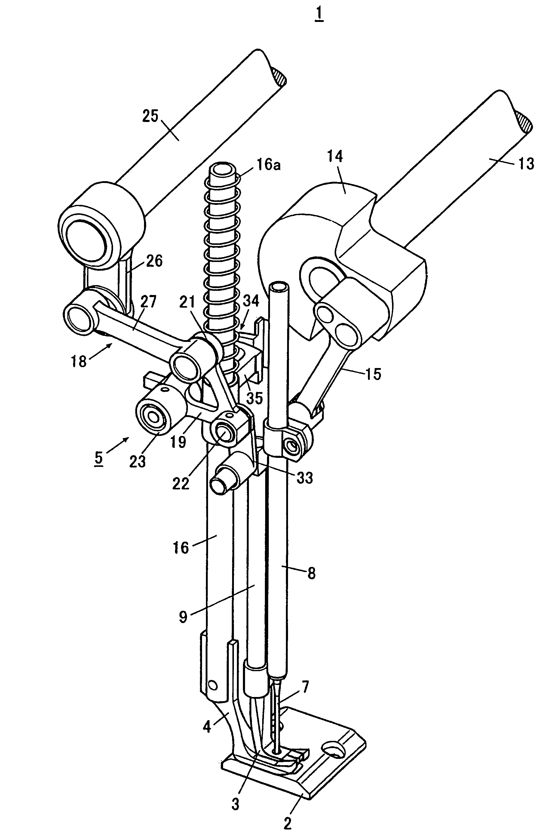
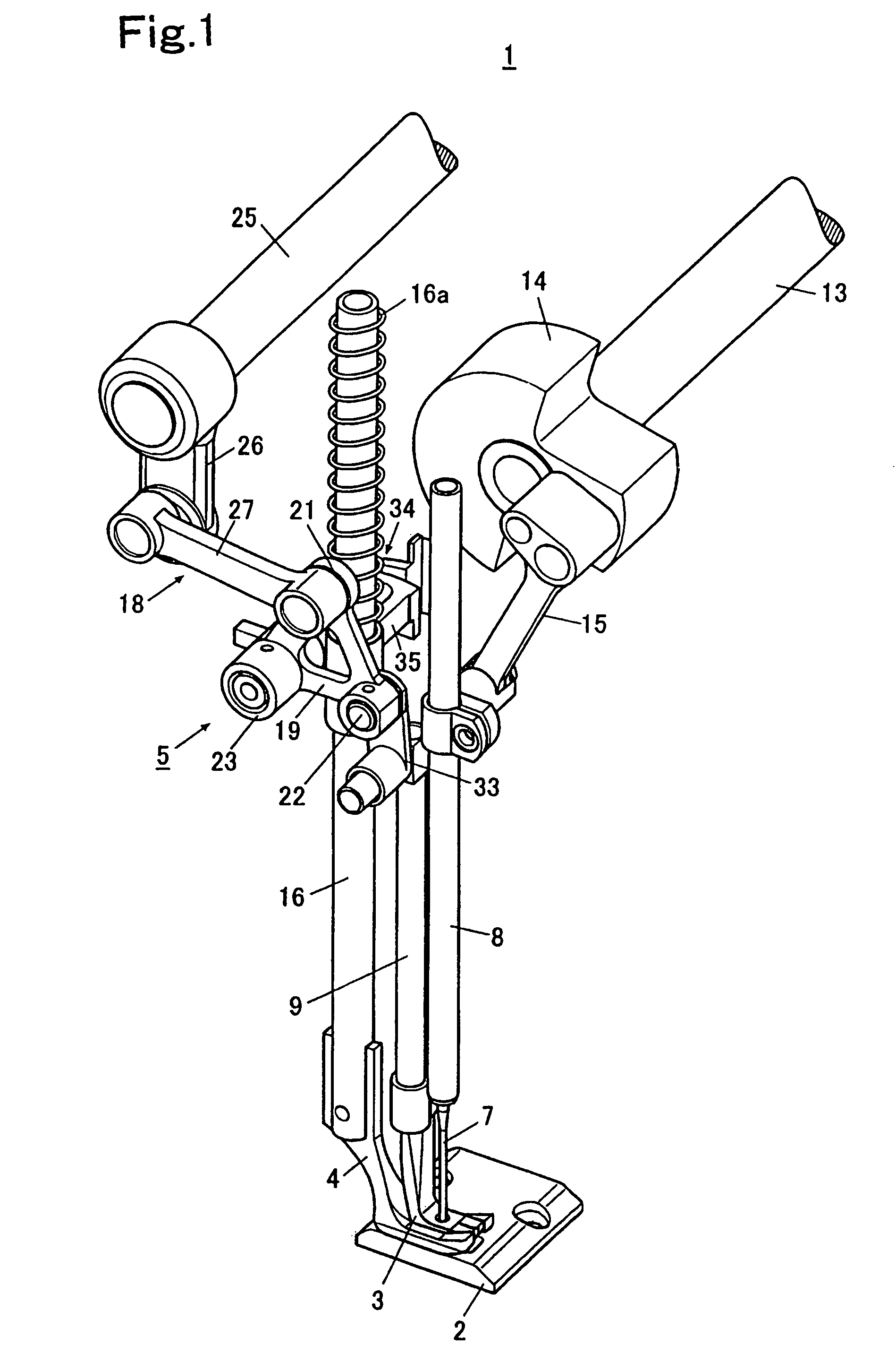
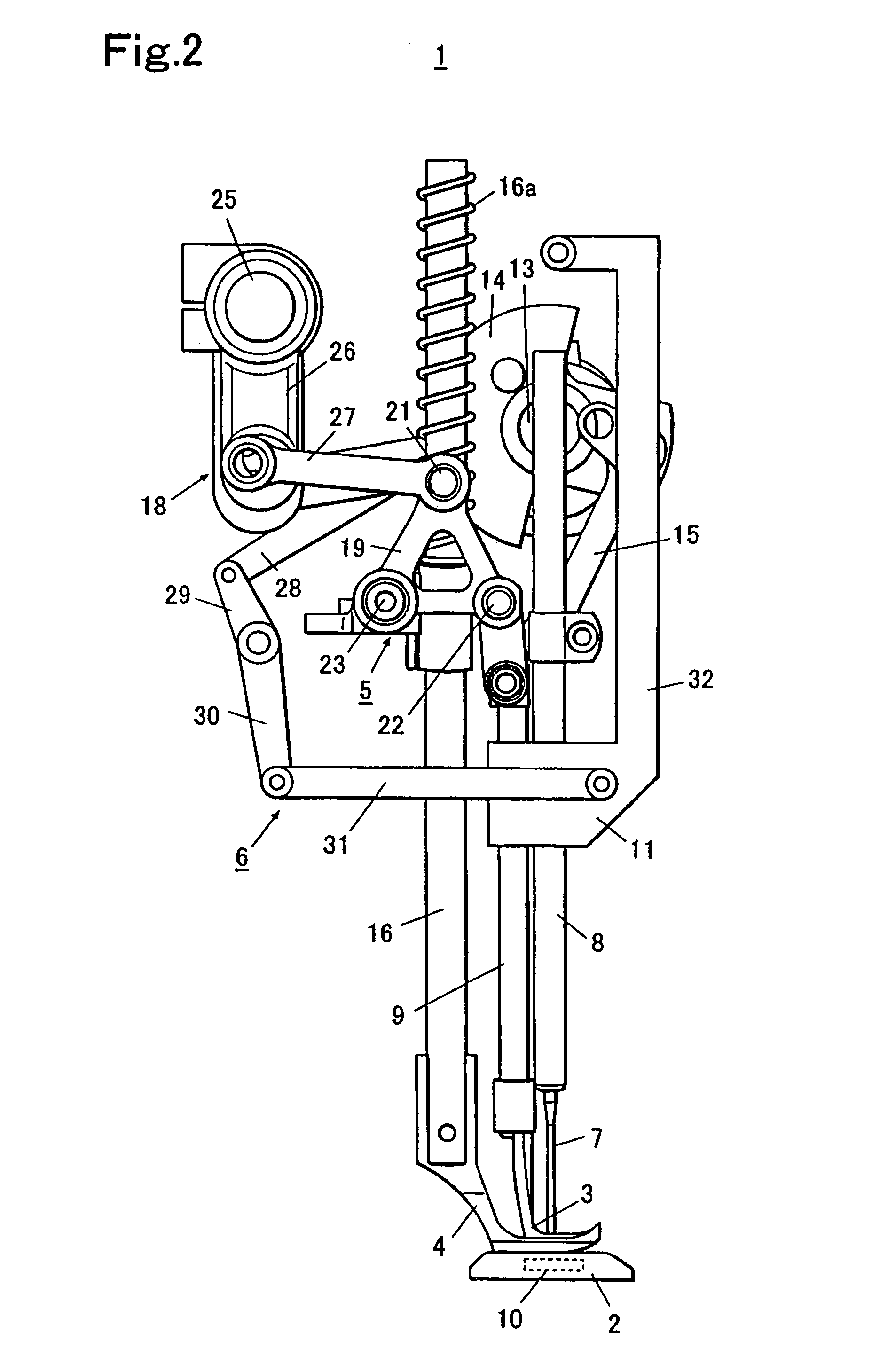
[0048]As shown in FIG. 1 through FIG. 3, a sewing machine 1 includes an upper feeding foot 3 operable to contact with a workpiece on a throat plate from above and operable to move in a cloth feeding direction so as to a feed the workpiece, a presser foot 4 operable to press the workpiece toward the throat plate 2 from above, a first operating mechanism 5 operable to move the upper feeding foot 3 and the presser foot 4 such that the upper feeding foot 3 and the presser foot 4 vertically reciprocate in opposite phases, and a second operating mechanism 6 operable to move the upper feeding foot 3 such that the upper feeding foot 3 reciprocates in the cloth feeding direction.

[0049]The upper feeding foot 3 is supported by a supporting bar 9 which extends in a vertical direction to be in line with a longitudinal direction of a needle bar 8. The needle bar 8 holds a needle 7 at a lower end thereof. The upper feeding foot 3 is operable to press the workpiece placed on the throat plate 2 from...

second embodiment

[0084]Next, a second embodiment of the invention will be explained. In the following explanation, portions that are the same as those of the sewing machine 1 of the first embodiment are attached with the same notations, and an explanation thereof will be omitted.

[0085]FIG. 11 is a perspective view showing a sewing machine 1C according to the second embodiment. As shown in FIG. 11, one end portion a lift lever 37c of the sewing machine 1C is separated from an extended portion 35 of the coupling member 34. By rotating the lift lever 37c, the one end portion and the extended portion 35 are brought into contact with each other or separated from each other.

[0086]FIG. 12 is a pneumatic circuit diagram with regard to an air cylinder 38c. As shown in FIG. 12, the air cylinder 38c is a cylinder of a one side rod type. Inside a space 38e on rod side of the air cylinder 38c, a spring 86 as a biasing member operable to bias the piston rod 39 in a rearward direction is housed. An inlet / outlet po...


PUM


Abstract

A sewing machine includes a needle, a needle bar which supports the needle, an upper feeding foot operable to feed the workpiece interlockingly with an up and down movement of the needle bar, a presser foot operable to press the workpiece, a holding bar which supports the presser foot, an actuator including an operating member operable to be changed to a first state, a second state or a no-load state, and a connecting portion which couples the operating member and the holding bar. The holding bar is constantly biased downward by a biasing force. The actuator moves the presser foot up against the first biasing force when the operating member is in the first state, and moves the presser foot down when the operating member is in the second state.

Description

[0001]The present invention claims priority from Japanese patent applications no. 2006-007496 filed on Jan. 16, 2006, and No. 2006-261049 filed on Sep. 26, 2006, the entire contents of which are incorporated herein by reference.BACKGROUND OF THE INVENTION[0002]1. Field of the Invention[0003]The present invention relates to a sewing machine for sewing a workpiece while feeding the workpiece with an upper feeding foot, a presser foot, and feeding teeth.[0004]2. Description of the Related Art[0005]In a sewing machine, as shown in FIG. 21A, when a needle 101 moves down and pierces a workpiece, an upper feeding foot 104 moves down at the same time. The upper feeding foot 104 holds the workpiece with feed teeth 105 which move up in its substantially elliptical oscillation motion.[0006]Next, as shown in FIG. 21B, when the upper feeding foot 104 presses the workpiece, a presser foot 106 which previously presses the workpiece starts to move up from the workpiece. At this time, the needle 101...

Claims


Application Information

Patent Timeline
Patent Type & Authority Patents(United States)
IPC IPC(8): D05B29/02D05B29/00
CPCD05B27/06D05B29/02D05D2207/02
Inventor NAGATA, YOSHIHIROSHIINA, TAKAYUKI
Owner JUKI CORP
Why Eureka
Try Eureka