Power tool having a transmission vent

a technology of power tools and vents, applied in the field of power tools, can solve problems such as leakage of transmission fluid, and achieve the effect of substantial loss of lubrican

Active Publication Date: 2011-05-24
AEG ELECTRIC TOOLS
View PDF18 Cites 0 Cited by
  • Summary
  • Abstract
  • Description
  • Claims
  • Application Information

AI Technical Summary

Benefits of technology

[0007]In view of the above discussion, it is an object of the present invention to further develop a power tool of the specified type so that a secure and permanent venting without any substantial loss in lubricant may be ensured.
[0009]A preferred embodiment of the present invention is based upon the notion to provide a meander-like sealing element in the path or channel taken by the air for the pressure compensation of the transmission box towards the atmosphere, which upon over- or underpressure allows air to circulate in the transmission box by extending the path from the transmission box to the outside, without any lubricant leaking from the transmission by capillary action.
[0011]According to a particularly preferred embodiment, the venting channel comprises an aperture open to the transmission box, wherein it is preferred that the sealing element substantially immediately adjoins the aperture. Thereby, leakage of lubricant from the transmission box is substantially avoided without the need for additional elements or laborious structures in order to seal other regions of the venting channel against leakage of the lubricant.
[0013]According to a particularly preferred embodiment the sealing element is configured in a way that it has a mouth opening facing the transmission box, that is an opening open directly or indirectly towards the transmission box. Further, two flow channels continuing from the mouth opening are provided so that air flowing out of the transmission box upon overpressure, for example, may flow into the mouth opening and from there flow in different directions into the two separate flow channels. This is especially expedient in order to avoid an accumulation of lubricant, for instance an accumulation of grease. In case of an accumulation of grease in the mouth opening, in a situation of overpressure the accumulated grease is pushed out of the mouth opening into only one of the two flow channels, so that there always remains a flow channel for air to flow through. This contributes to a reliable and secure venting.
[0014]Further, it is preferred that the sealing element comprises at least one, but preferably several levels (or stages) respectively composed of at least one (preferably only one) mouth opening leading into the respective level and two flow channels continuing from the mouth opening. By arranging several levels connected in series and configured in this manner, the above-mentioned advantage regarding the prevention of an accumulation of grease and a secure and reliable venting is ensured and, on the other hand, it is avoided that the lubricant (accumulated grease) finds its way to the point of leaking out of the power tool.

Problems solved by technology

If the transmission is lubricated by oil or an oil-like lubricant, there is the danger that the felt soaks up the oil through capillary action and that the transmission starts to leak after a short time (oil leakage by capillary action).
A similar problem arises also when using grease or grease-like lubricants.
However, the venting is necessary because the air pressure within the transmission housing of the hammer drill or chipping hammer is subject to continuous oscillations due to changes in temperature and the operation of the hammer mechanism, and a pressure compensation with the atmosphere has to be provided.

Method used


Image

  • Power tool having a transmission vent
  • Power tool having a transmission vent
  • Power tool having a transmission vent

Examples


Embodiment Construction

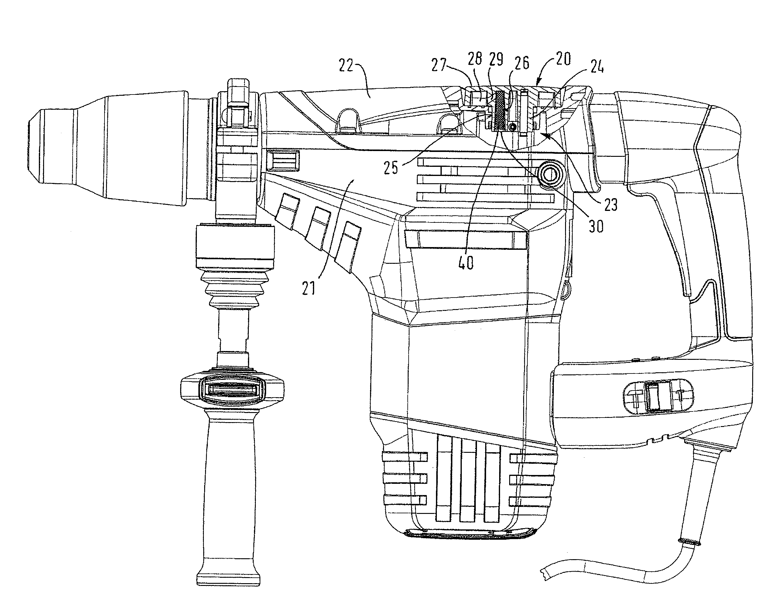
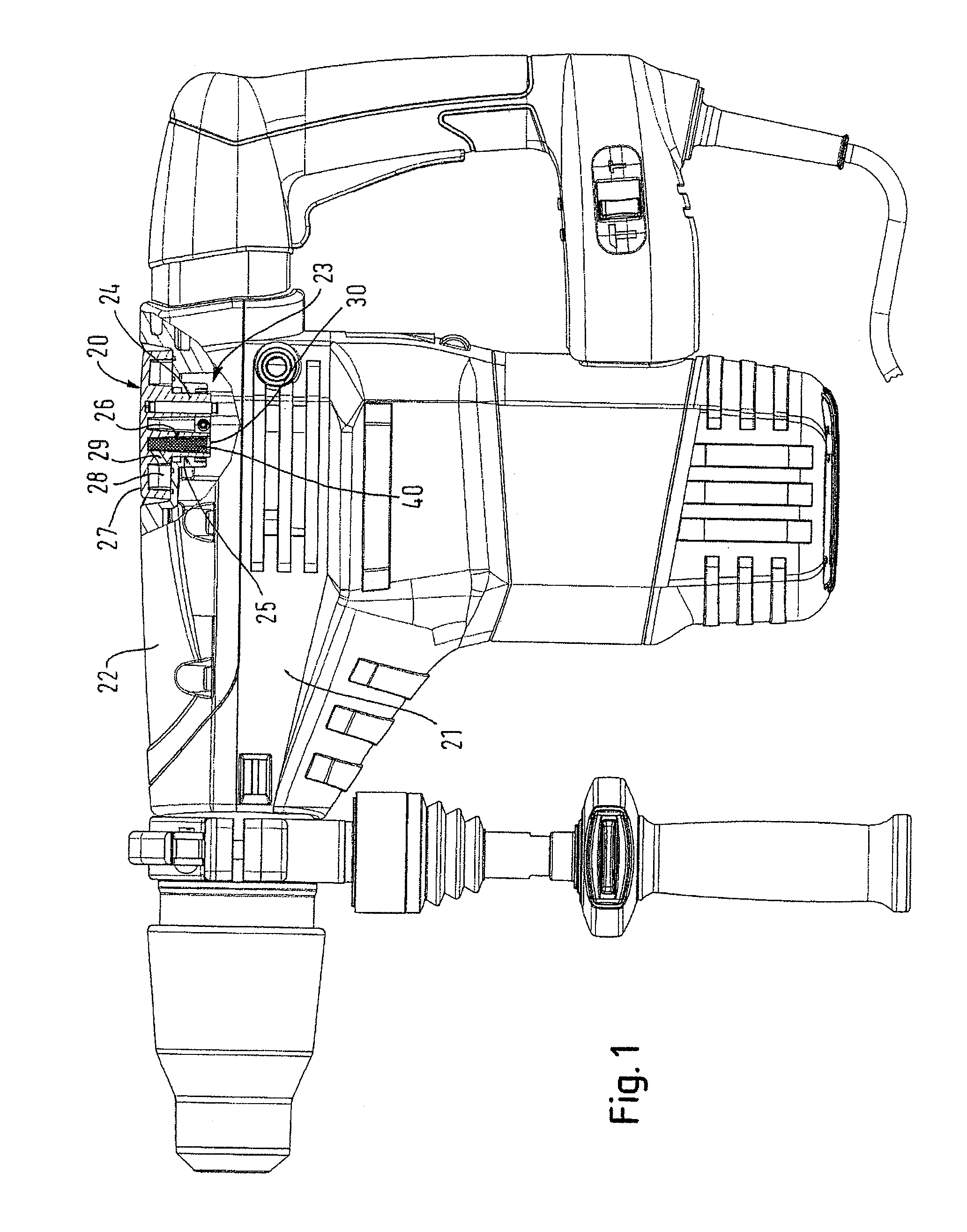
[0021]The illustrated power tool is a hammer drill and chiseling hammer comprising an electric motor (not shown) as drive unit, which offers a hammer drill or chiseling hammer function through a transmission (not shown). It is possible to switch between a hammer drill mode and chiseling hammer mode by means of a transmission switch 20. By virtue of a mechanical connection with the transmission, the transmission switch causes either the transmission of the rotational motion of the electric motor to the drill chuck (hammer drill mode) or causes a corresponding removal of this rotational motion (chipping hammer mode). The mechanical connection and the switching of the transmission is insubstantial for the present invention and, therefore, will not be explained in more detail. The transmission is received in a transmission housing which in the embodiment shown consists of a housing body 21 and a lid 22. A transmission box 23 is formed in the housing 21, 22, which in the present case hou...


PUM

PropertyMeasurementUnit
timeaaaaaaaaaa
thickaaaaaaaaaa
temperatureaaaaaaaaaa

Abstract

A power tool, such as a hammer drill and / or a chiseling hammer, includes a lubricated transmission arranged in a sealed transmission box. The transmission box is in fluid connection with the atmosphere via a venting channel. A sealing element is arranged in the venting channel. The sealing element cooperates with the venting channel to create a meandering pathway for air to pass through the venting channel so that leakage of lubricant between the sealing element and the venting channel is at least substantially prevented.

Description

RELATED APPLICATION[0001]This application is related to, and claims priority from, European Patent Application No. 08 010 192.6, filed Jun. 4, 2008, entitled “POWER TOOL HAVING A TRANSMISSION VENT,” the entirety of which is incorporated by reference herein and made a part of the present specification.BACKGROUND OF THE INVENTION[0002]1. Field of the Invention[0003]The present invention concerns a power tool, preferably a hammer drill or a chipping hammer comprising a lubricated transmission arranged in a sealed transmission box, in particular in an air-tight transmission box, wherein the transmission box is in fluid connection with the atmosphere via a venting channel, and an air-permeable sealing element arranged in the venting channel.[0004]2. Description of the Related Art[0005]Such a power tool is, for example, known from EP 1 252 976 A1, wherein the transmission box is open towards the atmosphere via a narrow channel and a filter connecting to this channel. The filter element ma...

Claims


Application Information

Patent Timeline
Patent Type & Authority Patents(United States)
IPC IPC(8): B25F5/02
CPCB01D45/06B23Q11/1069B25D17/20B25D16/006B25D2250/365B25D2250/185
Inventor ROBIEU, THOMAS
Owner AEG ELECTRIC TOOLS
Why Eureka
Try Eureka