
Device for projecting a stereo color image

Inactive Publication Date: 2006-02-21
INFITEC
View PDF6 Cites 88 Cited by
  • Summary
  • Abstract
  • Description
  • Claims
  • Application Information

AI Technical Summary

Benefits of technology

[0012]The invention is thus concerned with the task of providing a device for projection of a color image, which makes it possible not only to produce an enlarged color space, but rather also to reproduce it, wherein on the recording side the calculation is carried out relative to the reproduction side enlarged color space, wherein there is no substantial loss or penalty in image brightness, wherein the emitted light of the projection lamp is utilized in an efficient manner and wherein expensive spectrally pure light sources are not required.
[0013]It has been found that an alternative embodiment of the device can be employed for recording and reproducing three dimensional images. The device offers the advantage, that with few manipulative steps it is possible to alternate between the mode “image recording and reproducing with enhanced color reproduction faithfulness” and the mode “three dimensional recording and reproduction”.

Problems solved by technology

However the price for the thus achieved enlargement of the color space, for example in projection systems which use broad band emitting temperature radiators (bodies that deliver radiant heat, whose frequency (color) depends on the temperature, commonly used as wide-band strong sources of light) as projection lamps, is a substantial loss in image intensity.
However, such systems are very complex and expensive.
Besides this, the enlarging of the color space does not necessarily result in increased color reproduction fidelity.
Otherwise, there could result false colors which must be corrected using suitable color transformers.

Method used


Image

  • Device for projecting a stereo color image
  • Device for projecting a stereo color image
  • Device for projecting a stereo color image

Examples


Embodiment Construction

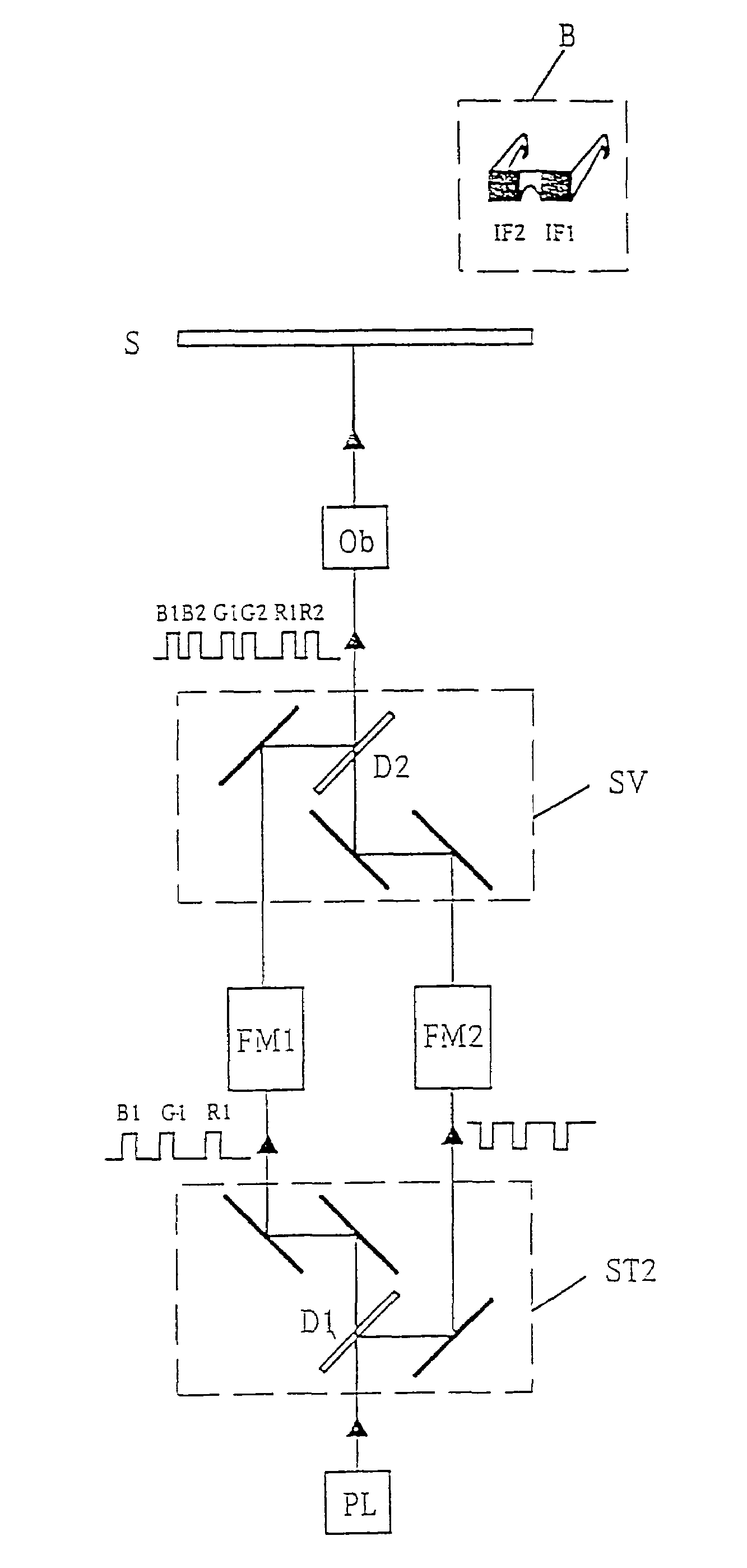
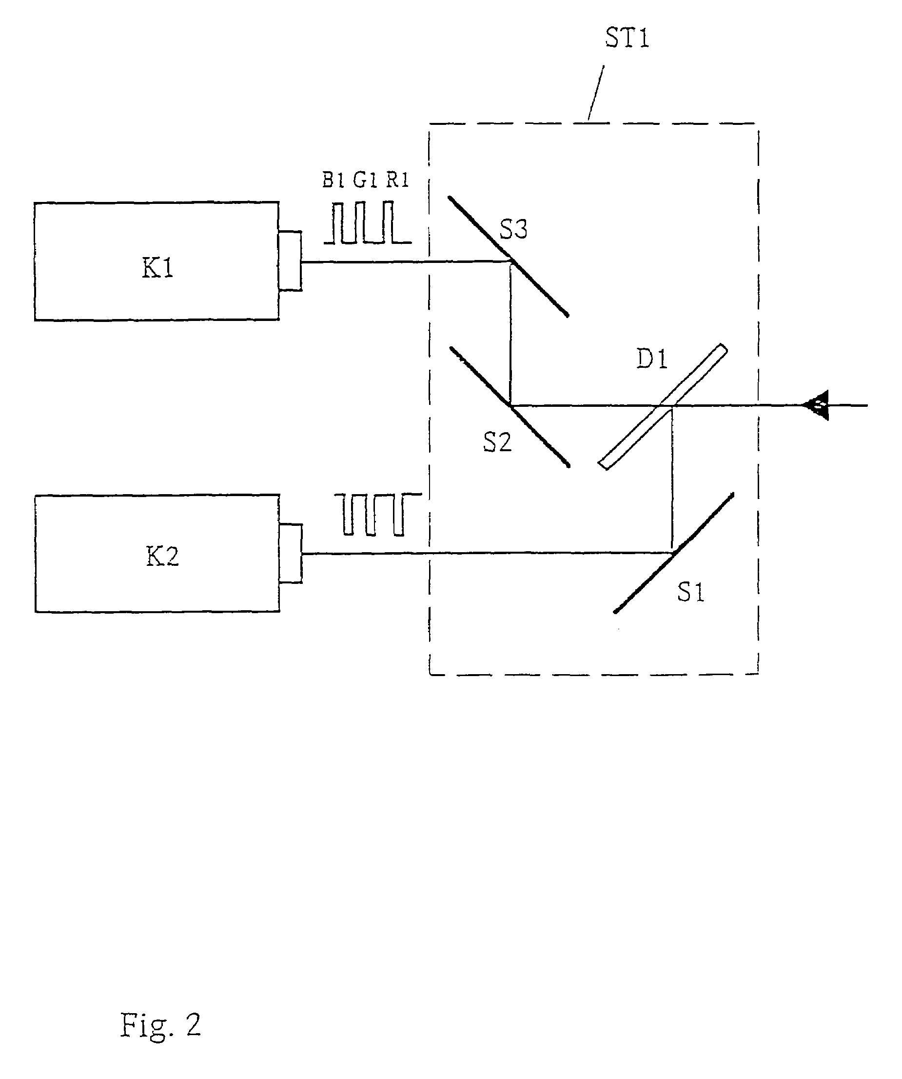
[0023]The invention will be described in the following on the basis of two illustrative embodiments which reference to the schematic drawings.

[0024]FIG. 2 shows an image recording system, comprised of a camera K1 and an camera K2 with a beam splitter ST1 placed before it, which is a single construction component comprised of the mirrors S1, S2, S3 and a dichroic mirror D1 with a transmission and reflection characteristic as shown in FIG. 3. The light from the object being recorded impinging upon D1 is spectrally separated into two partial light bundles. The partial light bundle passing through mirrors S2 and S3 into camera K1 is comprised spectrally of three components B1, G1, R1, which for example cover the wavelength ranges

[0025]

B1435–455 nmG1510–530 nmR1600–620 nm

[0026]The partial light bundle entering into camera K2 via mirror S1 is comprised of the spectrum complimentary to light bundle 1.

[0027]FIG. 4 shows a device for projection of a color image (also called image reproductio...


PUM


Abstract

A device for projecting a color image upon a screen, including color image recording and color image reproduction with an enhanced color reproduction trueness in comparison to conventional processes. In the device two images are recorded in parallel, which separately detect the shorter and the longer wavelength parts of the individual principle color spectral regions. In image reproduction six primary valences are produced, which respectively comprise the image information of the shorter and the longer wavelength parts of each of the individual principle color spectral regions. In an alternative embodiment the device produces a full color, stereoscopic image reproduction, in which the three primary valences of the respective shorter wave part encode a stereoscopic half image and the three primary valences of the respective longer wavelength part encode the other stereoscopic half image.

Description

CROSS REFERENCE TO RELATED APPLICATION[0001]This application is a Divisional of U.S. application Ser. No. 09 / 744,634 filed Jan. 26, 2001, which issued U.S. Pat. No. 6,698,890 on Mar. 2, 2004 which is a 371 of PCT / DE00 / 01666, filed May 24, 2000.BACKGROUND OF THE INVENTION[0002]1. Field of the Invention[0003]The invention concerns a device for projecting a color image onto a screen, the device enabling color image recording and a color image reproduction with greater fidelity than possible with existing techniques. In an alternative embodiment, the device and the therewith employed process provides for full color stereoscopic image reproduction.[0004]2. Description of the Related Art[0005]In existing devices and processes for image recording in full color, the color information is detected by the separate recording of the respective spectral regions which correspond to the primary colors red, green and blue. In the subsequent image reproduction, the primary color partial pictures are ...

Claims


Application Information

Patent Timeline
IPC IPC(8): G03B21/00G03B21/20G02B27/22G03B33/12G03B21/28G03B35/22H04N5/74H04N13/00H04N13/04H04N15/00
CPCG02B27/2207H04N9/3105H04N9/3197H04N13/0239H04N13/0257H04N13/0422H04N13/0431H04N13/0459H04N13/025H04N5/74H04N13/0048H04N19/597H04N13/0296H04N13/0497H04N13/324H04N13/257H04N13/161H04N13/296H04N13/334H04N13/363H04N13/239H04N13/25H04N13/398G02B30/23
Inventor JORKE, HELMUT
Owner INFITEC
Learn More