Modular structure of LED light source

a technology of led light source and module structure, which is applied in the direction of lighting and heating apparatus, instruments, lighting support devices, etc., can solve the problems of whittling down the efficacy of advertising light boxes, light source modules providing inferior illumination in a particular direction, and reducing the application scope of modular structures

Inactive Publication Date: 2011-05-24
CHINA ELECTRIC MFG CORP
View PDF12 Cites 16 Cited by
  • Summary
  • Abstract
  • Description
  • Claims
  • Application Information

AI Technical Summary

Benefits of technology

[0008]In view of the shortcomings of the conventional LED light source modules, the present invention proposes a modular structure of an LED light source, wherein the modular structure takes on a modular design and comes in a variety of dimensions, so that an integrated LED light source can be formed as desired in various sizes by assembling plural said modular structures having the appropriate dimensions. In consequence, potential inventory pressure brought by LED light sources of predefined sizes can be eliminated.
[0009]In the modular structure of the present invention, LEDs are arranged as an array of regular hexagons with an equal distance between every two adjacent said LEDs, so that the modular structure of the LED light source provides uniform illumination.
[0014]By implementing the present invention, at least the following progressive effects can be achieved:
[0015]1. The LEDs are arranged as regular hexagons so that the modular structure of the LED light source provides uniform illumination.
[0016]2. The modular structure of the LED light source takes on a modular design that allows a light source to be formed as desired in various sizes for different uses, thereby expanding the application scope of the modular structure.

Problems solved by technology

However, in consideration of the manufacturing costs and selling prices of LED light source modules, manufacturers usually prefer to put only LED light source modules of popular sizes into mass production because those customized LED light source modules of special sizes, having limited market demands, tend to burden the manufacturers with inventory pressure.
Therefore, improper arrangement of the LEDs causes the resultant LED light source module to provide inferior illumination in a particular direction.
Consequently, when such an LED light source module is used in an advertising light box, patterns and characters in certain areas of the advertising light box may look obscure due to insufficient illumination in that particular direction, thereby whittling down the efficacy of the advertising light box.

Method used


Image

  • Modular structure of LED light source
  • Modular structure of LED light source
  • Modular structure of LED light source

Examples


first embodiment

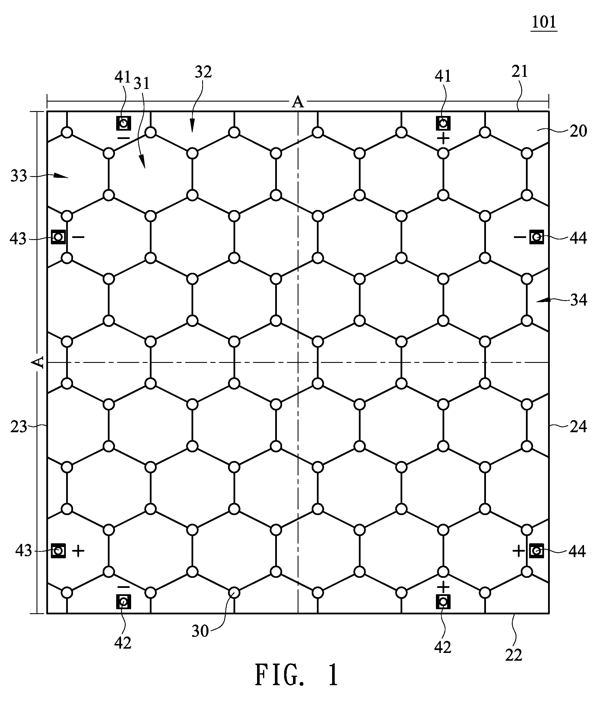
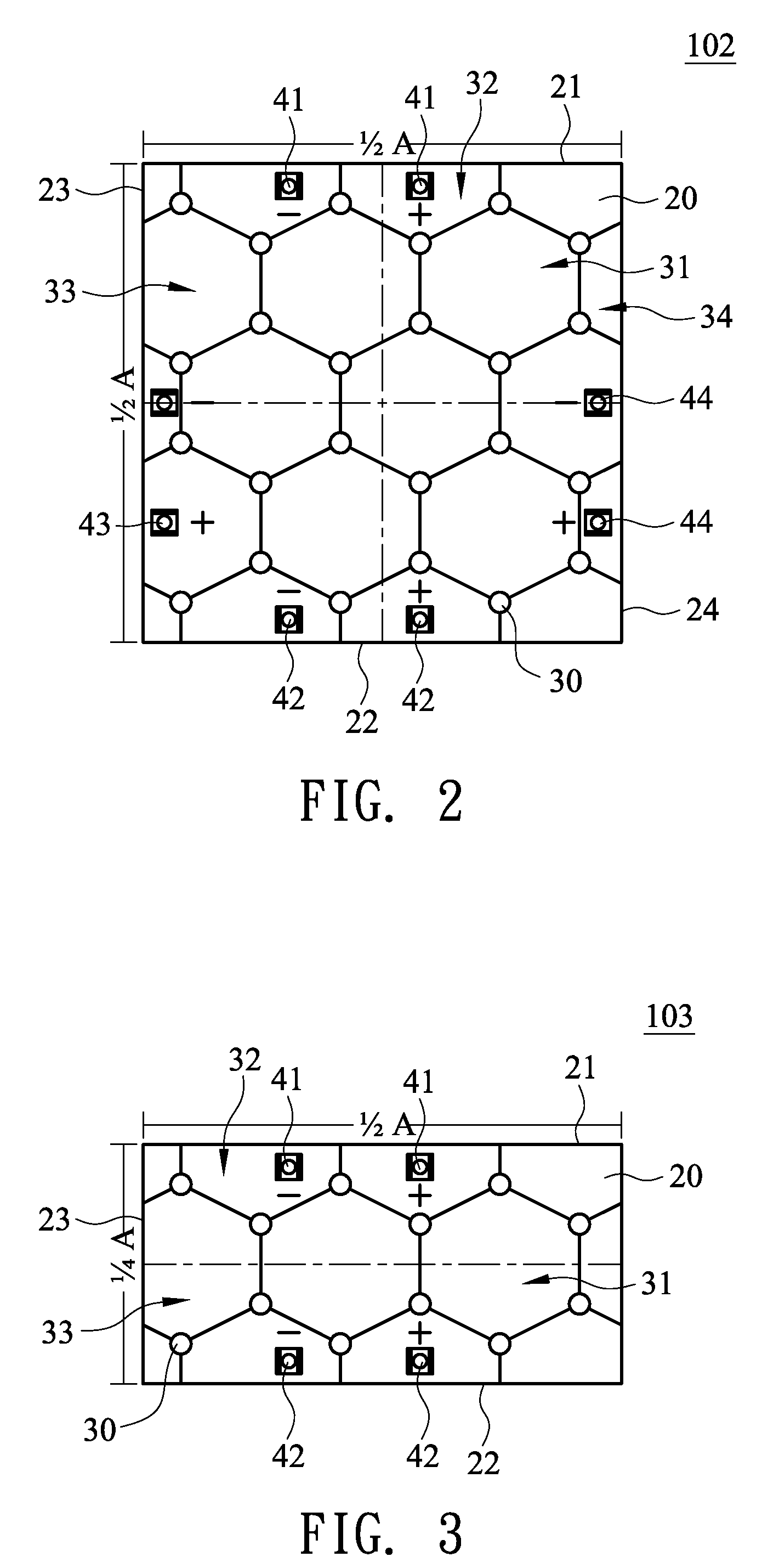
[0032]FIGS. 1 through 4 show some aspects of a first embodiment of the present invention, that is, a modular structure of an LED light source. As shown in the drawings, each modular structure 101, 102, 103, or 104 of an LED light source comprises a circuit board 20 and a plurality of LEDs 30.

[0033]The circuit board 20 has a quadrilateral shape defined by a first edge 21, a second edge 22, a third edge 23, and a fourth edge 24. The first edge 21 and the second edge 22 of the circuit board 20 are positioned opposite each other while the third edge 23 and the fourth edge 24 of the circuit board 20 are positioned opposite each other. As shown in FIG. 1, the first edge 21 and the second edge 22 are the upper and lower edges of the circuit board 20, respectively, while the third edge 23 and the fourth edge 24 are the left and right edges of the circuit board 20, respectively.

[0034]The circuit board 20 is a square circuit board, as shown in FIG. 1 or FIG. 2, or a rectangular circuit board,...

second embodiment

[0041]FIGS. 5 through 7 show some aspects of a second embodiment of the present invention. Therein, each modular structure 105, 106, or 107 of an LED light source comprises a circuit board 20′ and a plurality of LEDs 30.

[0042]The circuit board 20′ has a quadrilateral shape defined by a fifth edge 25, a sixth edge 26, a seventh edge 27, and an eighth edge 28, wherein the fifth edge 25 and the sixth edge 26 are positioned opposite each other while the seventh edge 27 and the eighth edge 28 are positioned opposite each other. Referring to FIG. 5, the fifth edge 25 and the sixth edge 26 are the upper and lower edges of the circuit board 20′, respectively, while the seventh edge 27 and the eighth edge 28 are the left and right edges of the circuit board 20′, respectively.

[0043]The circuit board 20′ is a rectangular circuit board, as shown in FIG. 5 or FIG. 6, or a square circuit board, as shown in FIG. 7. According to FIGS. 5 and 6, the circuit board 20′ further comprises a set of fifth ...

third embodiment

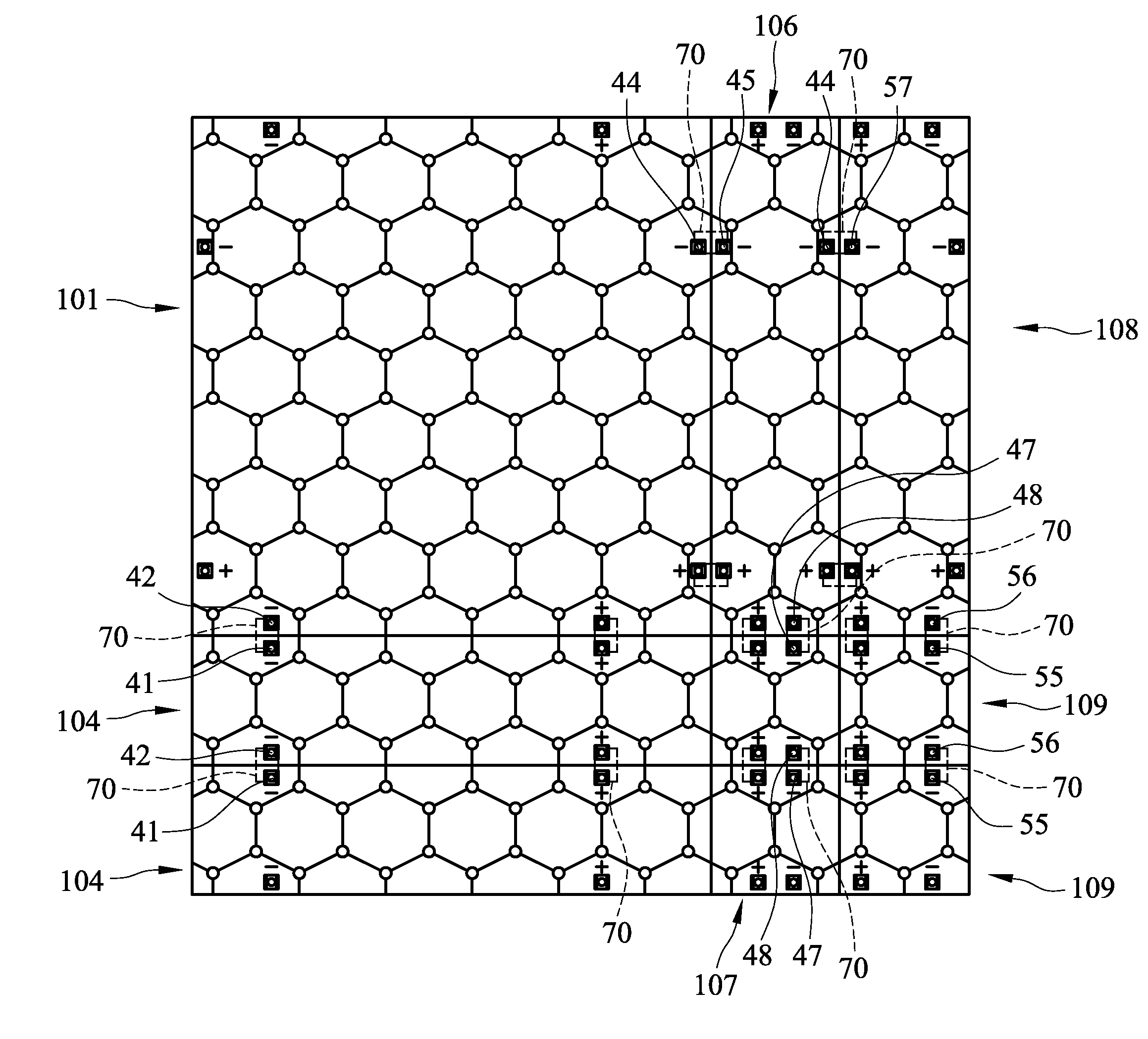
[0047]FIGS. 8 and 9 show some aspects of a third embodiment of the present invention. Therein, each modular structure 108 or 109 of an LED light source comprises a circuit board 20″ and a plurality of LEDs 30.

[0048]The circuit board 20″ has a quadrilateral shape defined by a ninth edge 51, a tenth edge 52, an eleventh edge 53, and a twelfth edge 54, wherein the ninth edge 51 and the tenth edge 52 are positioned opposite each other while the eleventh edge 53 and the twelfth edge 54 are positioned opposite each other. Referring to FIG. 8, the ninth edge 51 and the tenth edge 52 are the upper and lower edges of the circuit board 20″, respectively, while the eleventh edge 53 and the twelfth edge 54 are the left and right edges of the circuit board 20″, respectively.

[0049]The circuit board 20″ is a rectangular circuit board, as shown in FIG. 8, or a square circuit board, as shown in FIG. 9. According to FIGS. 8 and 9, the circuit board 20″ further comprises a set of ninth power connectio...


PUM


Abstract

A modular structure of a light-emitting diode (LED) light source is provided. The modular structure of the LED light source includes a circuit board and a plurality of LEDs. The LEDs are arranged on the circuit board as regular hexagons, with an equal distance between every two adjacent LEDs, so that the modular structure of the LED light source provides uniform illumination. Additionally, the modular structure of the LED light source takes on a modular design so as to form light sources of various sizes for different uses and thus have its application scope expanded.

Description

BACKGROUND OF THE INVENTION[0001]1. Technical Field[0002]The present invention relates to a modular structure of a light-emitting diode (LED) light source. More particularly, the present invention relates to a modular structure of an LED light source, wherein a plurality of the modular structures are capable of forming an integrated light source of various sizes.[0003]2. Description of Related Art[0004]For a long time in the past, light tubes have been used as the light source installed in most of advertising light boxes. However, in recent years, the prompt development of LED technology has enabled the mass production, and thereby lowering the selling prices, of LEDs, so that LEDs, with the descending selling prices in addition to their innate advantages such as having good shock resistance, being superior in power saving, being environmentally friendly, possessing compact volumes, enabling high-speed switching, and so forth, have shown great potential for replacing the traditional...

Claims


Application Information

Patent Timeline
Patent Type & Authority Patents(United States)
IPC IPC(8): F21S4/00F21V21/00
CPCF21S2/005G09F13/04G09F13/0409F21Y2101/02F21Y2105/001H05K1/142H05K1/181F21Y2105/10F21Y2115/10
Inventor LEE, HSIN-NUNG
Owner CHINA ELECTRIC MFG CORP
Why Eureka
Try Eureka