Continuous fiber brake rotor preform and apparatuses and methods for manufacturing same

a technology of brake rotor and continuous fiber, which is applied in the direction of cycle brakes, friction linings, cycle equipments, etc., can solve the problems of wasting 20 to 30 percent of cloth, affecting the quality of the cost of preforms made from woven and non-woven materials, etc., to achieve uniform and improved mechanical and structural properties, eliminate inventory and handling, and improve mechanical and structural properties uniform

Active Publication Date: 2016-09-15
BAM INC
View PDF5 Cites 5 Cited by
  • Summary
  • Abstract
  • Description
  • Claims
  • Application Information

AI Technical Summary

Benefits of technology

[0009]Advantageously, the continuous fiber brake rotor preform has more uniform and improved mechanical and structural properties than other preforms due, at least in part, to the continuous fiber output streams or filaments extending substantially between the preform's longitudinal first and second ends. The more uniform and improved mechanical and structural properties are also due, at least in part, to the varying radial distances of each continuous fiber output stream or filament relative to the preform's longitudinal axis within layers or flights and between longitudinally adjacent layers or flights. Also advantageously, the use of continuous fiber or filaments eliminates the need to inventory and handle of woven and non-woven annular segments and eliminates difficulties in carbonization attributable to woven materials.

Problems solved by technology

After needling, the structure formed in the second method is cut into toroidal-shaped preforms, resulting in twenty percent (20%) to thirty percent (30%) of the cloth being wasted.
Unfortunately, manufacturing woven and non-woven material from fiber is relatively expensive and, hence, preforms made from woven and non-woven material can be expensive.
Also, woven fabric material tends to block the diffusion of gases, thereby making the uniform addition of the carbon matrix to the preforms more difficult and causing the preforms to have carbon matrices that are not uniform throughout the preforms.
As a consequence, woven fabric material has an additional disadvantage in the manufacture of the preforms.
Such inventorying and handling are time-consuming and increase production costs.

Method used


Image

  • Continuous fiber brake rotor preform and apparatuses and methods for manufacturing same
  • Continuous fiber brake rotor preform and apparatuses and methods for manufacturing same
  • Continuous fiber brake rotor preform and apparatuses and methods for manufacturing same

Examples


Embodiment Construction

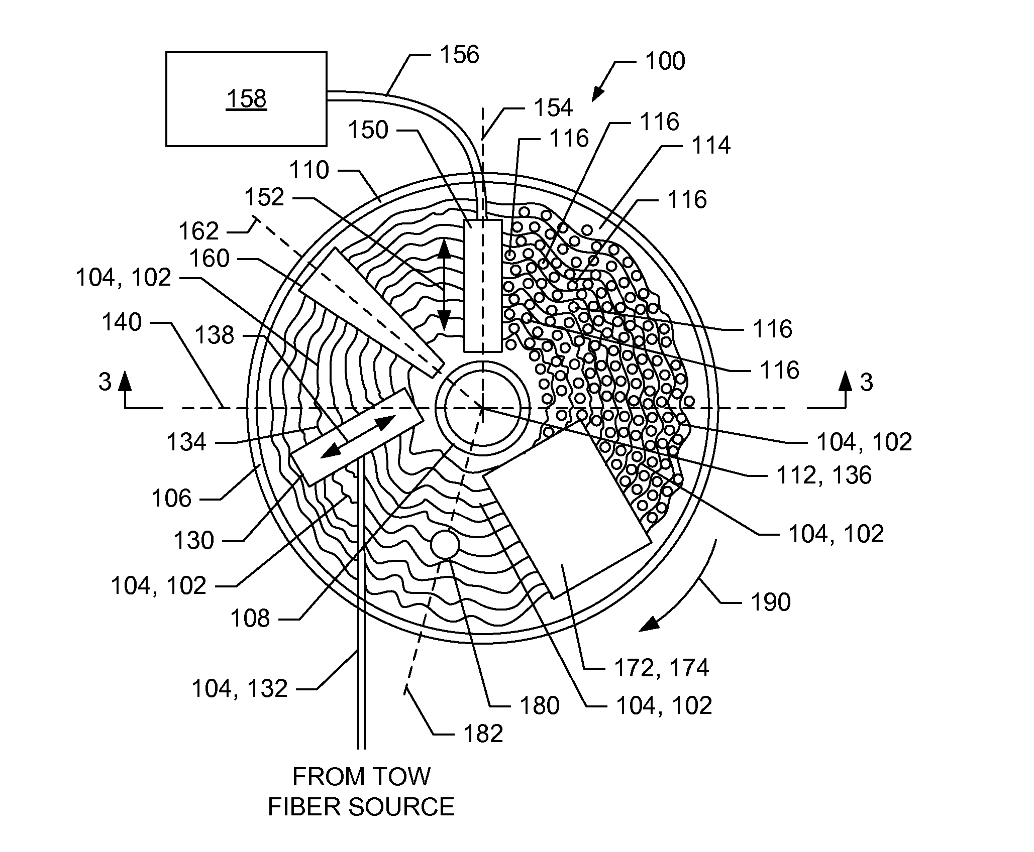
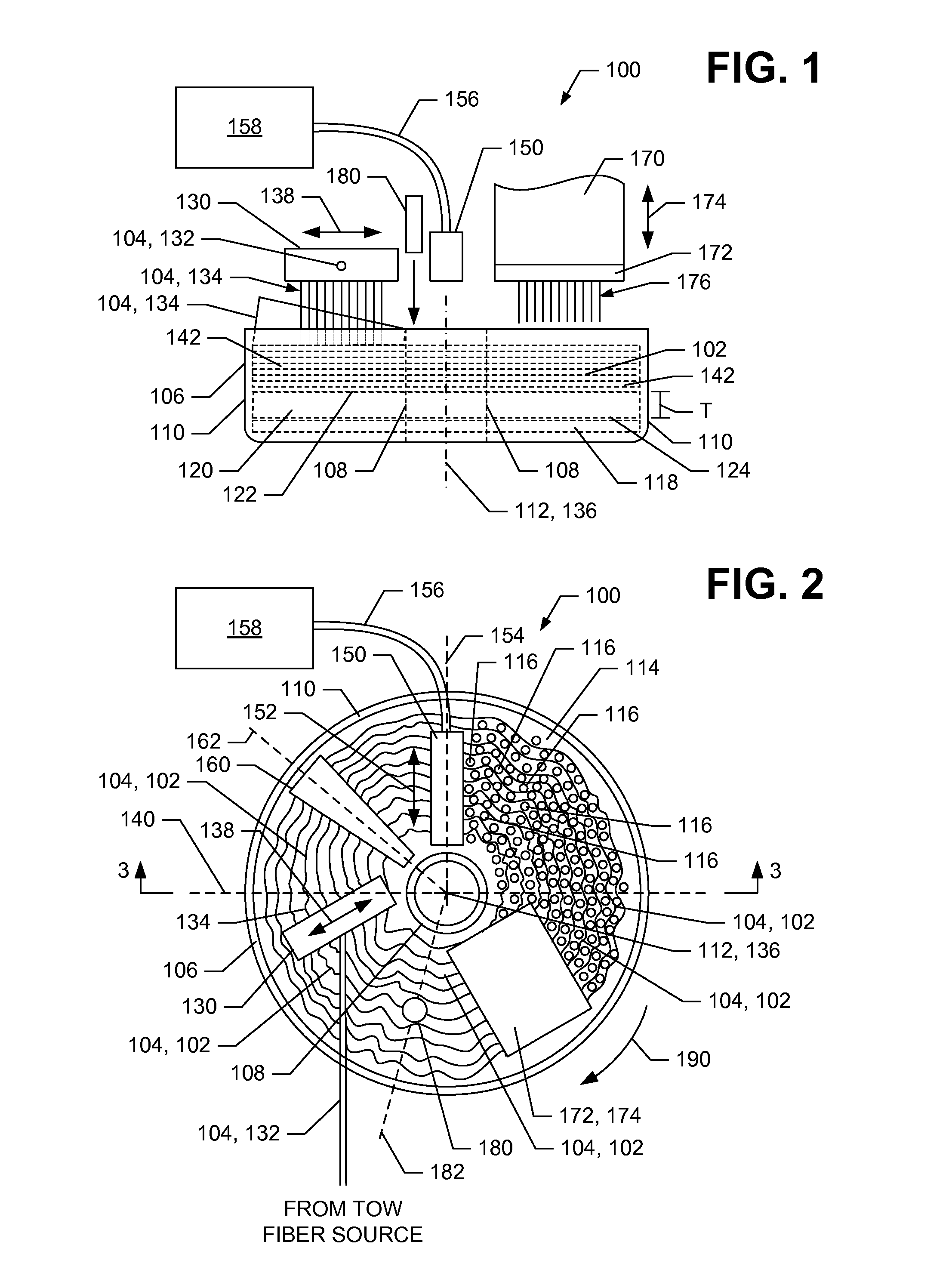
[0017]Referring now to the drawings in which like numerals represent like elements or steps throughout the several views, FIGS. 1 and 2 respectively display schematic, side and top plan views of certain components of an apparatus 100, in accordance with an example embodiment of the present invention, for manufacturing a continuous fiber brake rotor preform 102 (also sometimes referred to herein as a “preform 102”) substantially comprising tow fiber 104. The apparatus 100 (also sometimes referred to herein as a “needling machine 100”) includes a bowl 106 having a vertical inner wall 108 and vertical outer wall 110 that form a body of revolution about a central vertical axis 112. The bowl 106 defines an annular-shaped cavity 114 (see FIG. 2) extending between the inner and outer walls 108, 110 for the receipt of tow fibers 104 and, according to the example embodiment, staple fibers 116. The inner and outer walls 108, 110 are located at radii relative to the central vertical axis 112 t...


PUM

PropertyMeasurementUnit
temperatureaaaaaaaaaa
densitiesaaaaaaaaaa
densitiesaaaaaaaaaa

Abstract

A continuous fiber brake rotor preform and apparatuses and methods for manufacturing the preform are disclosed herein. The preform comprises a plurality of continuous fiber streams or filaments forming a substantially helical structure having layers or flights compressed together in the preform's longitudinal direction. Each continuous fiber stream or filament may comprise the same or different types of fiber, extends substantially between longitudinally disposed preform ends, and resides laterally adjacent to another continuous fiber stream or filament within each layer or flight of the helical structure. The radial distance between each continuous fiber stream or filament and the preform's longitudinal axis varies with angular location about the longitudinal axis. The preform further comprises web or z-direction fiber interspersed within the helical structure with certain of the web or z-direction fibers and continuous fiber streams or filaments extending at least partially in the longitudinal direction between the preform's layers or flights.

Description

FIELD OF THE INVENTION[0001]The present invention relates, generally, to the field of brake rotor preforms and to apparatuses and methods for manufacturing brake rotor preforms and similarly fabricated articles.BACKGROUND OF THE INVENTION[0002]Many high-performance brake rotors used in aircraft, automobiles, and other vehicles are manufactured from fibrous brake rotor preforms (also sometimes referred to herein as “preforms”). The preforms are typically formed using two methods. According to the first method, the preforms are made from layers of annular-shaped segments of woven and / or non-woven cloth having fibers extending in chordal, radial, or both directions, or having some other ordered structure. According to the second method, layers of woven or nonwoven cloth are combined to create an ordered structure with the in-plane fibers. In both methods, the layers are then needled together in the vertical direction with a needling machine in an attempt to form a unitary structure fro...

Claims


Application Information

Patent Timeline
Patent Type & Authority Applications(United States)
IPC IPC(8): F16D69/02D04H3/018D04H5/02D04H18/02D04H3/10D04H3/105
CPCF16D69/02D04H3/10D04H3/105F16D2200/0069D04H18/02D04H3/018D04H5/02B62L1/00D04H1/46D04H1/498Y10T428/213
Inventor SIMPSON, ALLEN
Owner BAM INC
Why Eureka
Try Eureka