Biosensor apparatus for detection of thermal flow

a biosensor and flow detection technology, applied in the field of biosensors, can solve the problems of difficult to combine the demands of the devices to be manufactured, the material and method used for electronic components require very high temperatures, and the design and fabrication of a custom integrated biosensor unit is expensiv

Active Publication Date: 2011-05-24
SENZIME
View PDF11 Cites 10 Cited by
  • Summary
  • Abstract
  • Description
  • Claims
  • Application Information

AI Technical Summary

Benefits of technology

[0004]In order to eliminate the drawbacks associated with the prior art device and to eliminate the need of using thermostatting, a novel bio sensor apparatus is provided comprising a housing made of an insulating material in conjunction with the specially designed heat sinks and heat reflectors. When the analysis is to be carried out the biosensor unit itself is easily connected and brought in thermal contact with the transducer unit in the instrument.
[0008]The term “generally flat” as used hereinafter indicates that at least the reaction chamber of such a biosensor unit should be flat in the meaning that the thickness of such a chamber and the opposite large walls enclosing it is substantially smaller than the dimensions of said large walls. The transducer unit as well as the biosensor unit shall be designed so as to enable a continuous flow of a sample of bio fluid through the reaction chamber. Therefore, the transducer unit as well as the biosensor unit comprises suitable channels for this purpose. Heat produced by the reaction between substrates in the fluid and enzymes is transmitted via the opposite large walls of the chamber to the respective Peltier element, thereby making it possible to measure the concentration of the substrate.

Problems solved by technology

It has turned out that there is a significant cost of designing and fabricating a custom integrated biosensor unit that includes both the biological sensing part and the necessary electronic elements.
One major reason for this is that the materials and methods used for electronic components require very high temperatures, which temperature levels are incompatible with the fabrication of the biological part.
It has turned out to be difficult to combine these contradicting demands of the devices to be manufactured.
However, it has turned out that this transducer technology could have a drawback of being sensitive, in some cases, to interference from rapid and sudden temperature and heat radiation changes in the environment and therefore making it less useful in these cases.

Method used


Image

  • Biosensor apparatus for detection of thermal flow
  • Biosensor apparatus for detection of thermal flow
  • Biosensor apparatus for detection of thermal flow

Examples


Embodiment Construction

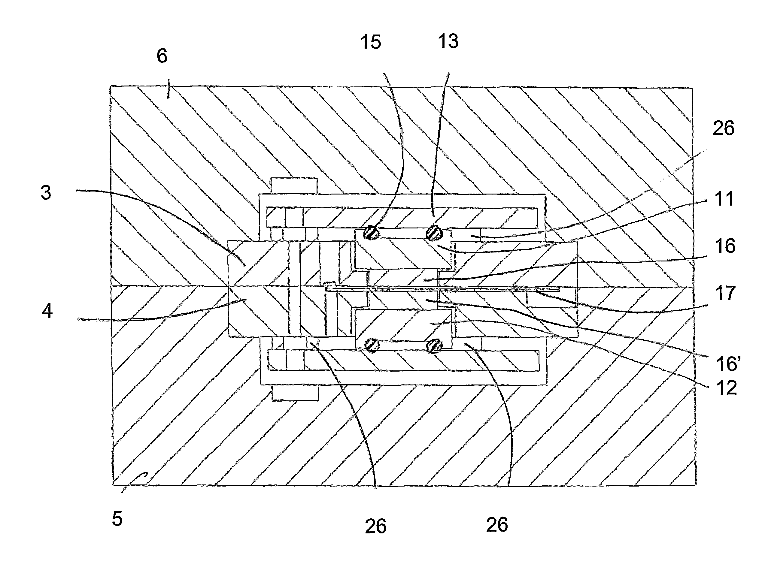
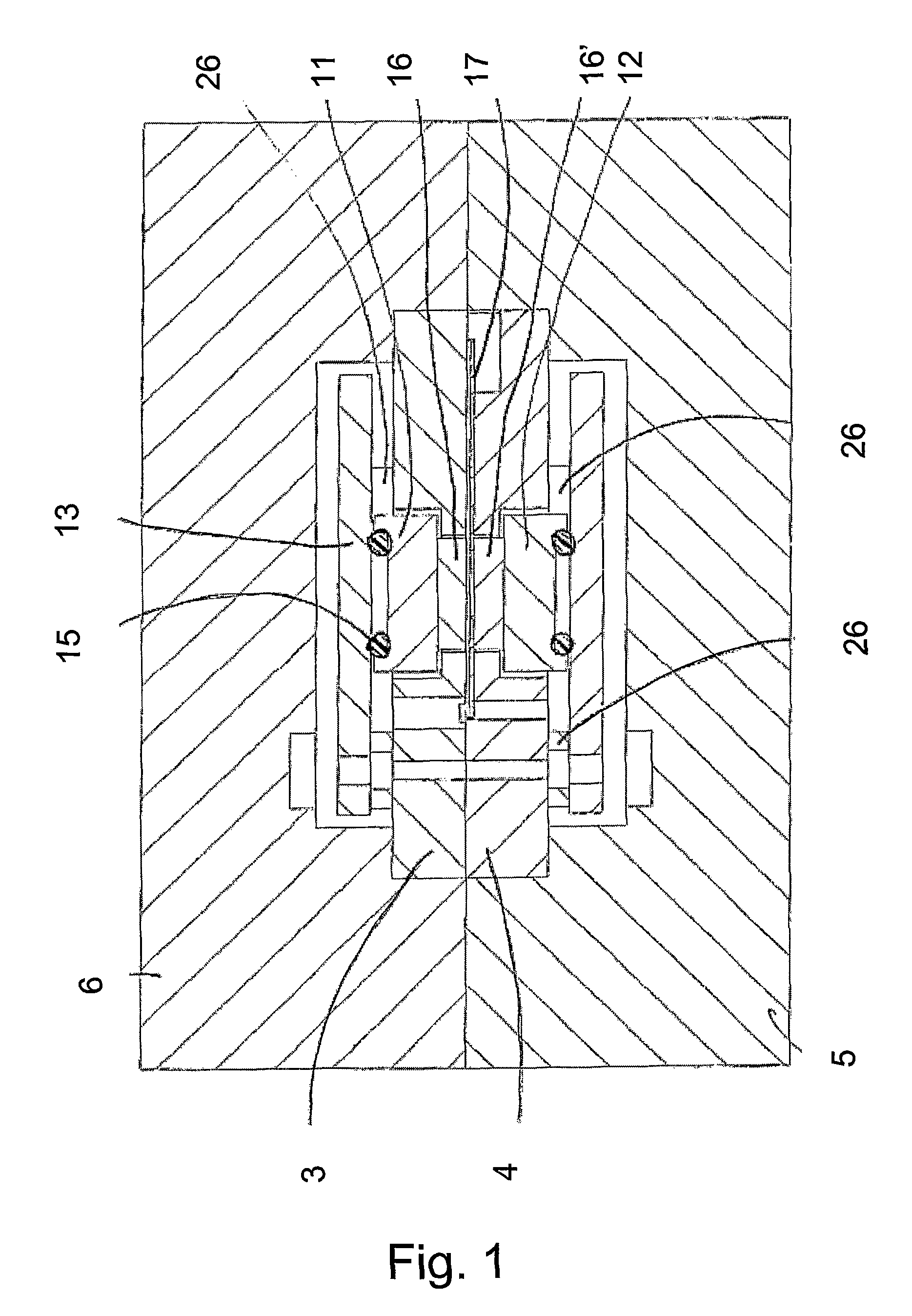
[0024]In FIG. 1 the apparatus according to the invention is shown in a cross-sectional view.

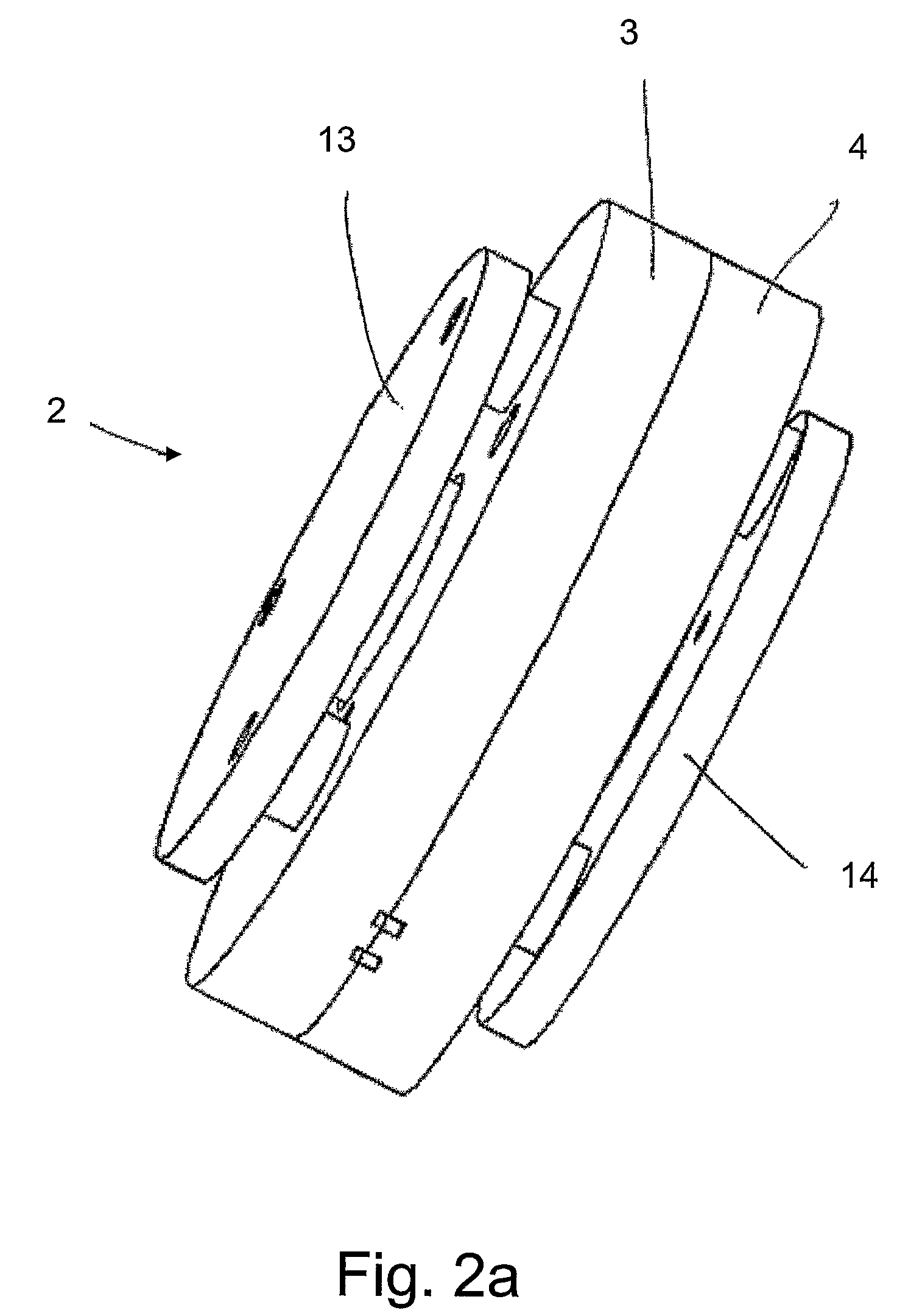
[0025]In general terms the biosensor apparatus according to the invention comprises a housing consisting of two housing blocks, a first housing block 5, and a second housing block 6. These two blocks are made of a thermally insulating material, i.e. having low thermal conductivity in assembled state they form an inner compartment housing the active devices, i.e. a transducer unit and a biosensor unit comprising a reaction chamber, and generally indicated with reference numeral 2 in FIG. 2 (to be further described below with reference to FIGS. 2a-2c). In the reaction chamber reactions generating heat can be performed. There are two heat sinks 11, 12 made of a material with heat capacity and heat diffusivity large enough to absorb and dissipate the heat flow from the enzymatic reaction quickly with only a slight, negligible disturbance in the temperature of the inner compartment, to render thei...


PUM

PropertyMeasurementUnit
timeaaaaaaaaaa
timeaaaaaaaaaa
timeaaaaaaaaaa

Abstract

In general terms the biosensor apparatus according to the invention comprises a housing (5, 6), a pair of heat sinks (11, 12) and a pair of heat reflectors (13, 14) thermally floating relative to the heat sinks, and a pair of Peltier elements (16) attached to and in thermal contact with the heat sinks (11, 12), one element (16) on each heat sink (11, 12). The housing is made of an insulating material, and the heat sinks (11, 12) are made of a material with thermal properties large enough to absorb the heat flow with only a very slight, negligible disturbance in its temperature, to render their envelope surface having a high heat emissivity. The heat reflectors (13, 14) are made of a material having a very low emissivity and have a generally flat and thin disc shaped structure and acts primarily as radiation shields.

Description

[0001]The present invention relates to biosensor systems in general, and in particular to a thermal flow transducer type of system, especially for enzymatic serial reactions.BACKGROUND OF THE INVENTION[0002]The term biosensor is commonly referred to as a measuring device that combines a biological sensing part in close proximity to a non-biological transducer which converts the biochemical information produced in the biological part into a measurable signal.[0003]The most commonly employed transducer in current biosensor instruments (e.g. a clinical analyser) is electrochemically based. The analyser is often used in connection with a biosensor unit (one-time use), which before operation, is connected to the analyser. The biosensor unit contains both the biological and the electronic part. It has turned out that there is a significant cost of designing and fabricating a custom integrated biosensor unit that includes both the biological sensing part and the necessary electronic elemen...

Claims


Application Information

Patent Timeline
Patent Type & Authority Patents(United States)
IPC IPC(8): G01N25/20
CPCG01K17/006G01N25/20
Inventor CARLSSON, THOMAS
Owner SENZIME
Why Eureka
Try Eureka