
Heater unit and battery structure with heater

a battery structure and heater technology, applied in the direction of furnaces, lighting and heating apparatus, electrochemical generators, etc., can solve the problems of insufficient output power, inability to provide adequate output power, and inability to generate sufficient output power in low-temperature conditions

Inactive Publication Date: 2011-05-24
PANASONIC EV ENERGY CO LTD
View PDF21 Cites 1 Cited by
  • Summary
  • Abstract
  • Description
  • Claims
  • Application Information

AI Technical Summary

Benefits of technology

[0009]The present invention has been made in view of the above circumstances and has an object to provide a heater unit and a battery structure with heater, arranged to heat the battery structure appropriately, and prevent the temperature of the heater (part or whole of the heater) itself from excessively increasing.

Problems solved by technology

However, the batteries such as nickel-metal hydride storage batteries have problems that discharge capacity is apt to decrease during cold conditions, failing to provide adequate output power.
If such battery is used as a power source of an electric vehicle, a hybrid electric vehicle, or the like, for instance, it could not generate sufficient output power in low-temperature conditions, e.g., in a cold region where temperatures may fall to sub-zero.
However, the technique disclosed in the above publication '367 may not heat the battery sufficiently.
In some cases, deformation such as warp or distortion occurs in a bottom of a container made of a heat insulating material.
If the sheet heater is also deformed, warped or distorted due to the deformation of the container, a gap is likely to be formed between the sheet heater and the battery.
In this case, furthermore, the heat of the sheet heater is hard to conduct to the battery.
This may cause an excessive increase in temperature of the sheet heater (part or whole of the heater) itself.

Method used


Image

  • Heater unit and battery structure with heater
  • Heater unit and battery structure with heater
  • Heater unit and battery structure with heater

Examples


Embodiment Construction

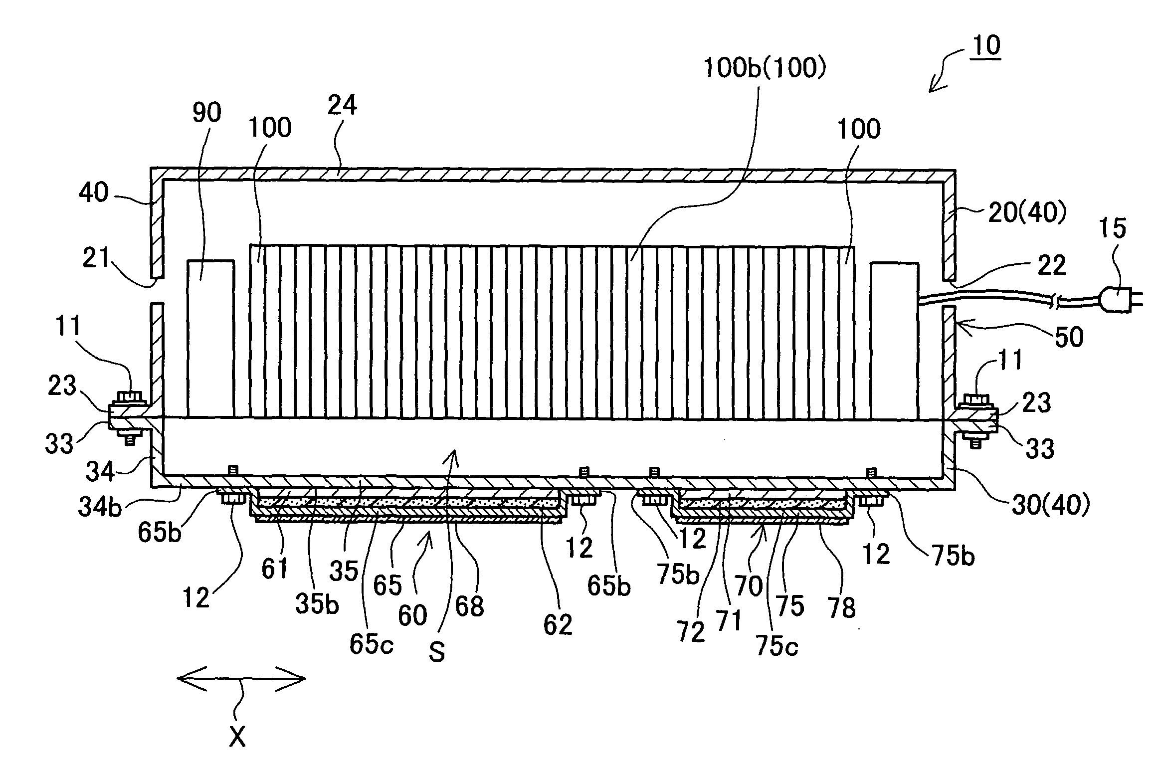
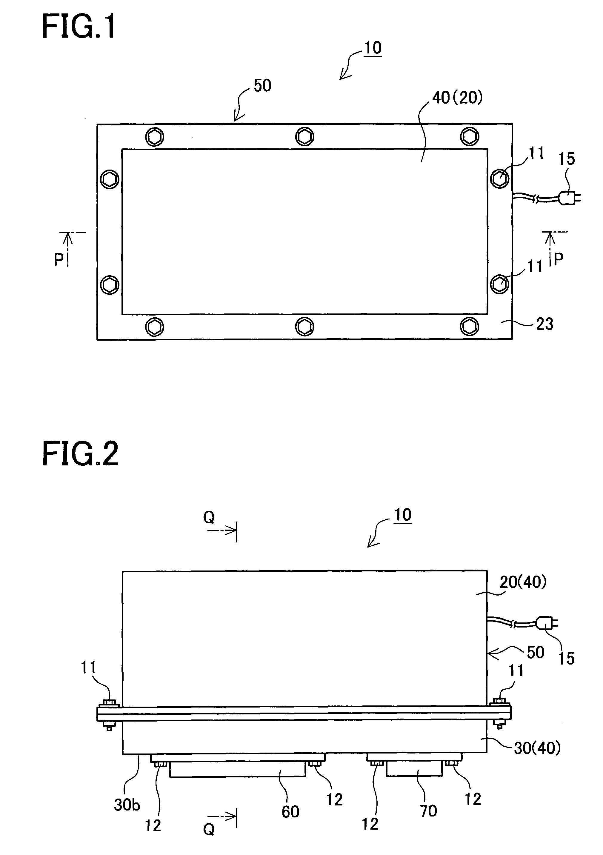
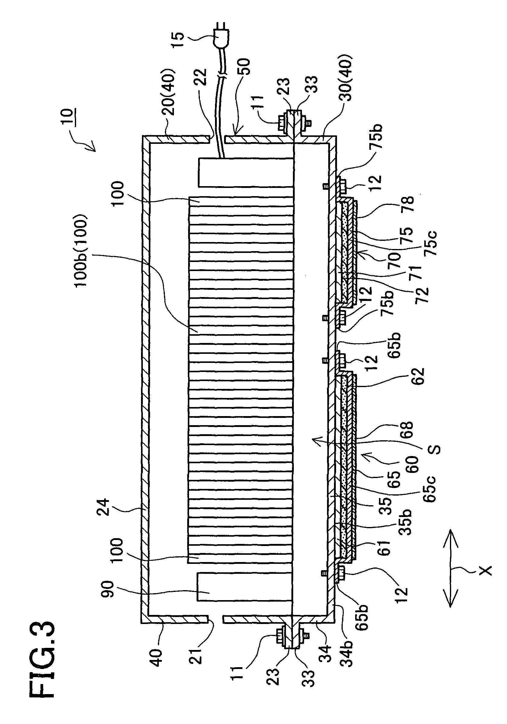
[0051]A detailed description of a preferred embodiment of a battery structure with heater (hereinafter, referred to as a “heater-equipped battery structure”) 10 according to the present invention will now be given referring to the accompanying drawings.

[0052]The heater-equipped battery structure 10 includes a battery pack 50, a first heater unit 60, and a second heater unit 70 as shown in FIGS. 1 and 2.

[0053]The battery pack 50 includes a housing case 40 constituted of a first housing member 20 and a second housing member 30, and a plurality of secondary batteries 100 (forty batteries in the present embodiment) housed in the housing case 40, as shown in FIG. 3. In the present embodiment, the battery pack 50 corresponds to a battery structure.

[0054]Each secondary battery 100 is a nickel-metal hydride storage sealed battery provided with a battery case 101, a positive terminal 161 and a negative terminal 162, as shown in FIG. 4. The battery case 101 has a resin case body 102 of a near...


PUM

PropertyMeasurementUnit
thicknessaaaaaaaaaa
elastic forceaaaaaaaaaa
temperatureaaaaaaaaaa

Abstract

There are provided a heater unit and a battery structure with heater, which are capable of heating the battery structure appropriately and preventing a heater (part or whole of the heater) itself from excessively increasing in temperature. A first heater unit is provided with a first sheet heater, a first holding member holding it, and a first sheet placed between a lower surface of a first heater and the first holding member in such a manner as to be deformable in at least a direction of thickness of the first heater. The first heater is deformed when the first heater unit is fixed to the battery pack 50, thereby pressing the lower surface of the first heater to bring an upper surface of the first heater into close contact with an outer surface (a surface to be heated) of a spaced part of the battery pack.

Description

BACKGROUND OF THE INVENTION[0001]1. Field of the Invention[0002]The present invention relates to a heater unit and a battery structure with heater including the heater unit.[0003]2. Description of Related Art[0004]Batteries such as nickel-metal hydride storage batteries have been watched as power sources of portable devices and power sources of electric vehicles, hybrid electric vehicles, and others.[0005]However, the batteries such as nickel-metal hydride storage batteries have problems that discharge capacity is apt to decrease during cold conditions, failing to provide adequate output power. If such battery is used as a power source of an electric vehicle, a hybrid electric vehicle, or the like, for instance, it could not generate sufficient output power in low-temperature conditions, e.g., in a cold region where temperatures may fall to sub-zero.[0006]In recent years, some techniques for solving the above problems by attaching a heater to a battery to heat the battery by use of ...

Claims


Application Information

Patent Timeline
Patent Type & Authority Patents(United States)
IPC IPC(8): H05B1/00H01M10/613H01M10/60H01M10/615H01M10/617H01M10/623H01M10/625H01M10/647H01M10/651H01M10/653H01M10/6563H01M10/6571H01M10/658
CPCH05B3/267
Inventor SUZUKI, MASAHIKOFUKUSAKO, NAOKIOKUDA, JUNUEMURA, YUKIEKANAMARU, KUNIO
Owner PANASONIC EV ENERGY CO LTD
Learn More