
Decompressing type heater, its heating method, and electronic product manufacturing method

a heating method and decompression type technology, applied in the field of decompression type heaters, can solve problems such as voids and and achieve the effects of peeling of the joint portion and generating holes in the solder joint portion

Active Publication Date: 2012-09-18
TOYOTA JIDOSHA KK +1
View PDF21 Cites 1 Cited by
  • Summary
  • Abstract
  • Description
  • Claims
  • Application Information

AI Technical Summary

Benefits of technology

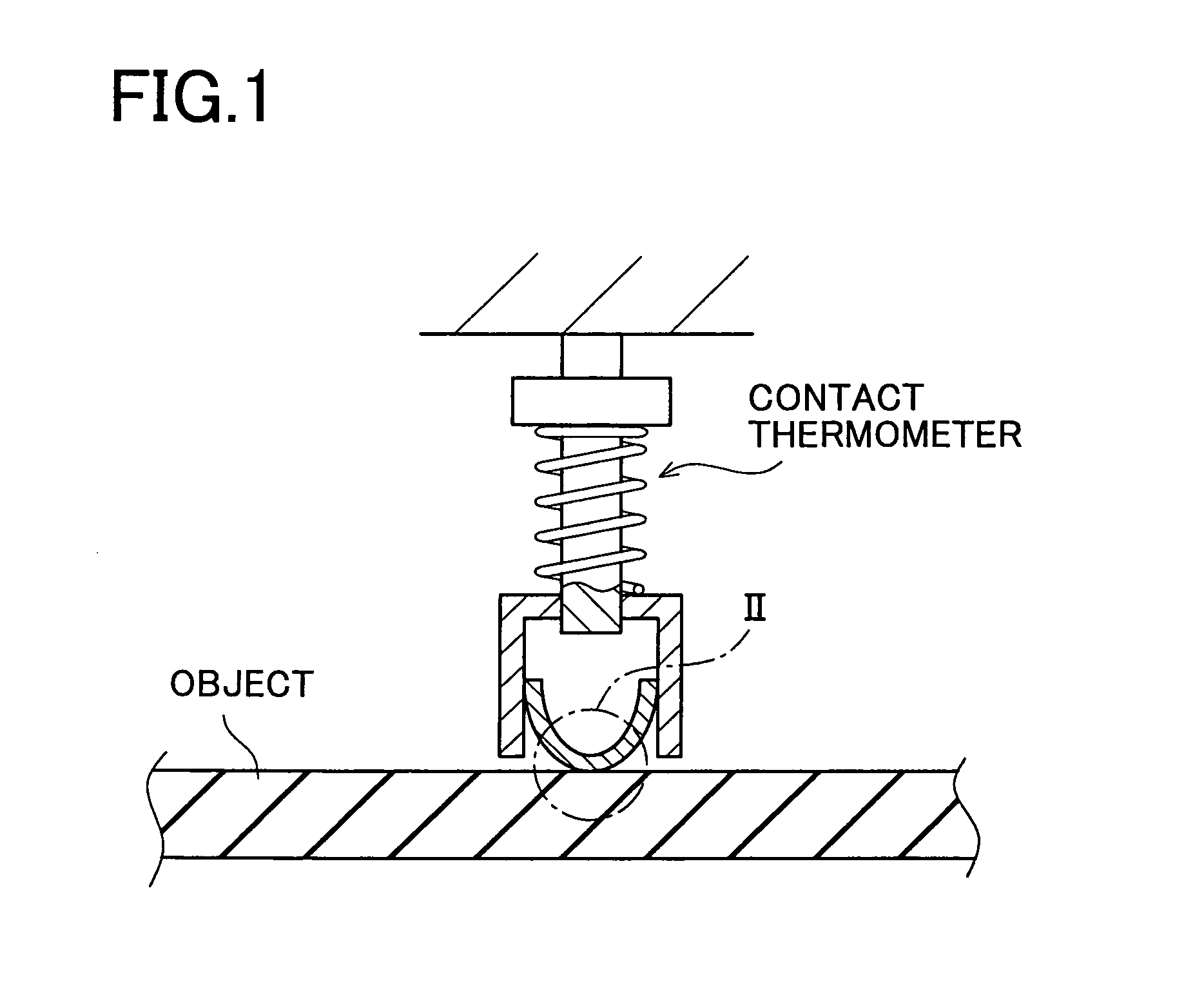
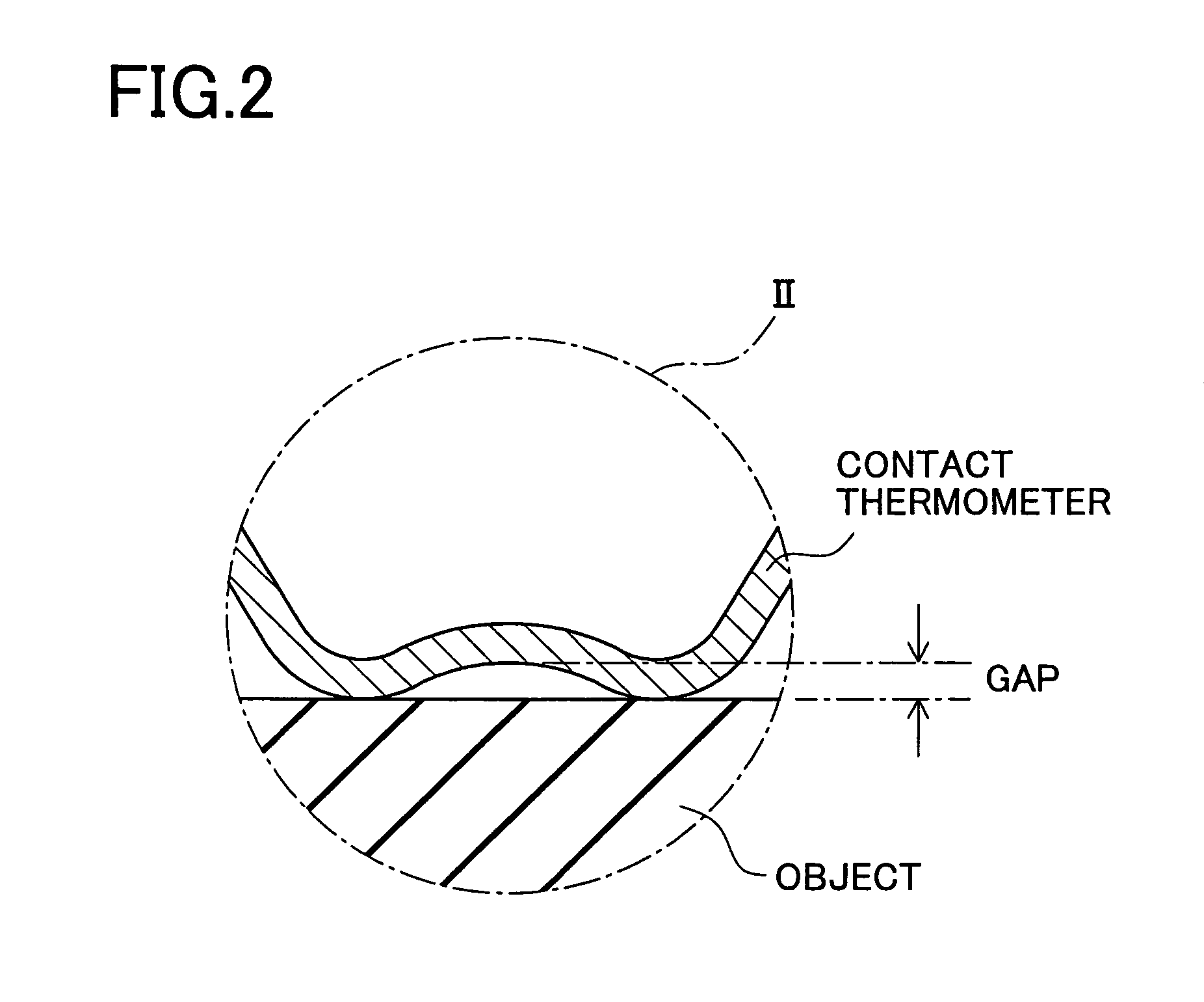
The present invention relates to a heater and a heating method for solder joining electronic components under lowered pressure. The invention solves the problem of accurately measuring the temperature of the object being heated under lowered pressure, as the pressure in the heater changes and affects the thermal conductivity of the gap between the object and the contact thermometer. The invention provides a decompressing type heater with a heat treatment chamber and a controlling part for adjusting the non-contact temperature measuring part to eliminate the difference of the measured value with the contact temperature measuring part during pre-heating under atmospheric pressure and to control the heater based on the measured value of the adjusted non-contact temperature measuring part during heat treatment under lowered pressure. The heater can accurately measure the temperature of the object and perform heat treatment under accurate temperature control based on the actual temperature of the object.

Problems solved by technology

In this solder joining using such heating method, however, holes (hereinafter, referred to as voids) may be generated in a solder joint portion.
The presence of the voids may cause peeling of the joint portion or a decrease in heat conduction efficiency from the second joining member (the electronic component) to the first joining member (the substrate).

Method used


Image

  • Decompressing type heater, its heating method, and electronic product manufacturing method
  • Decompressing type heater, its heating method, and electronic product manufacturing method
  • Decompressing type heater, its heating method, and electronic product manufacturing method

Examples


Embodiment Construction

[0044]A detailed description of a preferred embodiment of the present invention will now be given referring to the accompanying drawings. This embodiment embodies the present invention about a decompressing type heater, a heating method thereof, and a method of manufacturing an electronic product by using them.

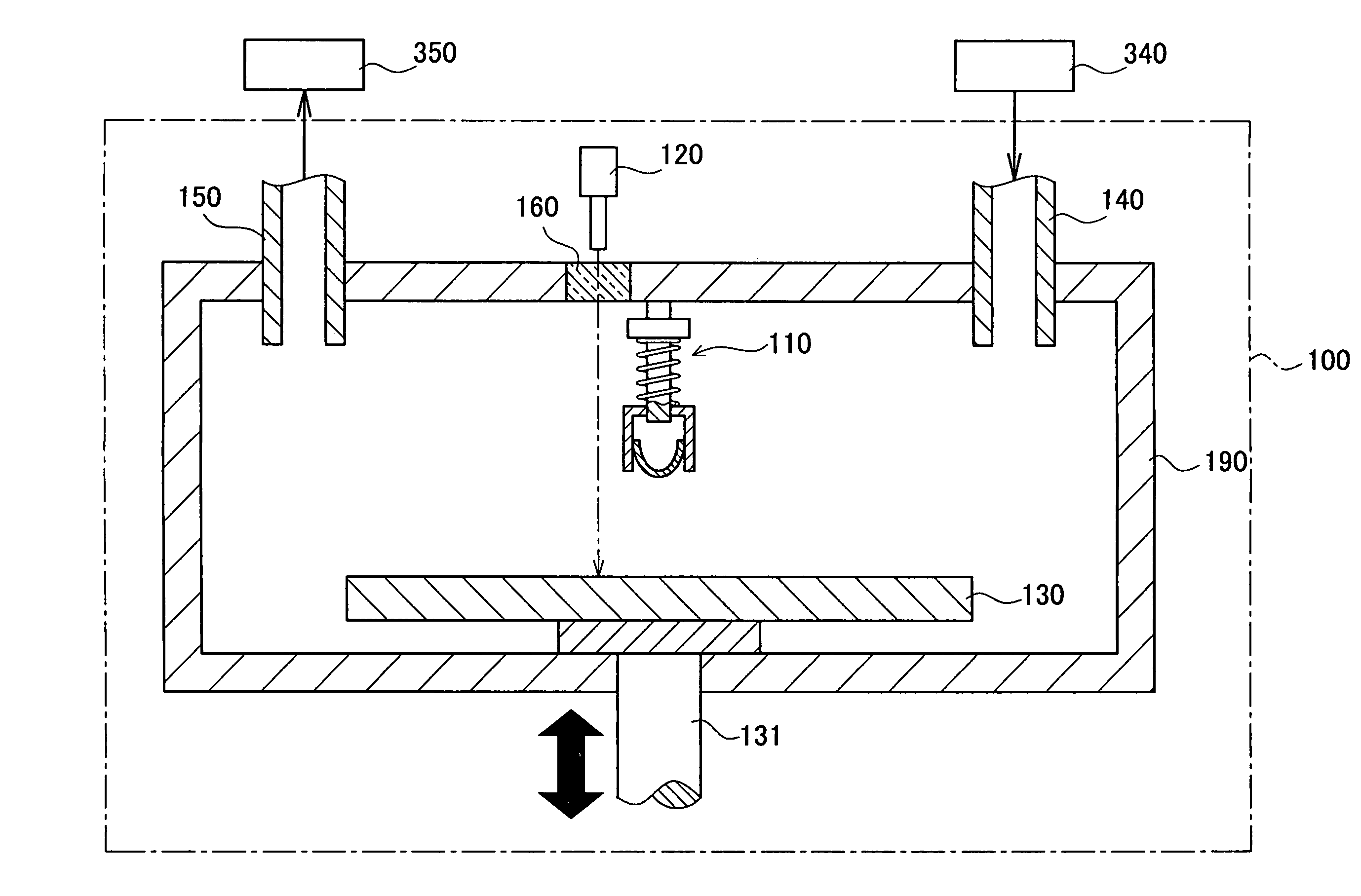
[0045]The decompressing type heater is first explained below. As shown in FIG. 3, a decompressing type heater 100 includes an inlet port 140, an outlet port 150, a contact temperature measuring part 110, a radiation thermometer 120, a heater 130, a cylinder 131, a quartz window 160, and a chamber 190.

[0046]The decompressing type heater 100 is arranged to perform heat treatment of an object to be heated in the chamber 190. The chamber 190 is a heat treatment chamber which is air-tightly closed during heat treatment and the internal atmosphere is replaced through the outlet port 150 and the inlet port 140 for atmosphere replacement. Furthermore, the chamber 190 is configured to ...


PUM

PropertyMeasurementUnit
pressure P1aaaaaaaaaa
liquidus temperatureaaaaaaaaaa

Abstract

An object is heated to a preheating temperature in an atmosphere of a reducing gas under the atmospheric pressure while adjusting the setting of the emissivity of a non-contact temperature measuring part and regulating the temperature of the object according to the measured value measured by a contact temperature measuring part. The pressure of the atmosphere is reduced. The object is further heated to a heating temperature under a lowered pressure while regulating the temperature of the object according to the measured value measured by the non-contact temperature measuring part whose setting of the emissivity is adjusted during the heating process to the preheating temperature. The pressure of the atmosphere is increased back to the atmospheric pressure while maintaining the heating temperature of the object. The temperature of the object is decreased under the atmospheric pressure. With this, in the process of heating an object under a lowered pressure, the actual temperature of the object is managed over the whole steps, and the object can be most suitably heated according to the actual temperature.

Description

TECHNICAL FIELD[0001]The present invention relates to a heating technique for heating an object under lowered pressure. For example, the present invention relates to a heater for solder joining a board and an electronic product under lowered pressure and a heating method thereof. Furthermore, the present invention relates to a method of manufacturing an electronic product by the heater.BACKGROUND ART[0002]As a method of manufacturing an electronic product to be manufactured by solder joining a first joining member (e.g. a substrate) and a second joining member (e.g. an electronic component), there is a method achieved by supplying solder to the first joining member, placing the second joining member thereon, and heating them to be soldered to each other in a heater. In this solder joining using such heating method, however, holes (hereinafter, referred to as voids) may be generated in a solder joint portion. The presence of the voids may cause peeling of the joint portion or a decre...

Claims


Application Information

Patent Timeline
Patent Type & Authority Patents(United States)
IPC IPC(8): G06F19/00
CPCG01J5/0003G01J5/0044G01J5/08G01J5/0846G01K1/143G01K13/00H05K3/3494H05K2203/111H05K2203/163H05K3/34B23K1/00G01J5/00
Inventor OL, SOTAROMATSUURA, MASANARIKUBOTA, TOMOYUKITSURUTA, MASAYA
Owner TOYOTA JIDOSHA KK
Learn More