Livestock stall system

a technology of livestock and stalls, which is applied in the direction of lighting and heating apparatus, renewable energy machines, heating types, etc., can solve the problems of unsatisfactory hot air heating, uneven temperature of litter (bedding), global environmental degradation, etc., and achieve the effect of preventing the deterioration of litter

Inactive Publication Date: 2020-09-10
MAYEKAWA MFG CO LTD
View PDF0 Cites 1 Cited by
  • Summary
  • Abstract
  • Description
  • Claims
  • Application Information

AI Technical Summary

Benefits of technology

[0010]According to the livestock stall system configured as described above, the temperature of the floor surface of the livestock stall is adjusted by the medium that circulates through the inside of the pipe. For this reason, floor heating and floor cooling can be appropriately adopted. For this reason, it is possible to take measures against the cold of winter and the heat of summer, while maintaining the livestock stall in a favorable environment and preventing the deterioration of the litter (bedding). Further, it is possible to provide a comfortable livestock stall not only in winter and summer, but also throughout the year.

Problems solved by technology

In particular, since newborn chicks are fragile, the newborn chicks need to be kept in a high-temperature close to body temperature and calm environment.
The hot air heating is undesirable because irradiating the chicks with wind will take the body temperature away from the chicks.
In addition, the brooder heating is undesirable because it uses fossil fuels and generates carbon dioxide, which leads to global environmental degradation.
In addition, in a gas brooder method used for heating, since local heating is applied, the temperature of the litter (bedding) becomes uneven, and the condition of the litter (bedding) deteriorates.
In addition, exhaust gas, soot, and the like also have an effect on ecology, and it is difficult to make the whole stall a suitable environment.
In the case of spraying the mist, when the humidity is high, it is not possible to use the heat of vaporization and it is difficult to appropriately cool the stall.
Further, in the case of directly sprinkling the water on the livestock, since the litter (bedding) gets wet, the condition of the litter (bedding) deteriorates.
The floor heating is favorable for such heating, but in a case of lowering the temperature in the livestock stall, there is an only method of naturally cooling the livestock stall and there is a poor response to an ever-changing external environment.
In addition, the floor heating can heat the entire floor, but in the case of lowering the temperature, there is an only method of naturally cooling the floor and it is difficult to adjust to a suitable temperature.

Method used


Image

  • Livestock stall system
  • Livestock stall system
  • Livestock stall system

Examples


first embodiment

[0020]A first embodiment of the present invention will be described with reference to FIGS. 1 to 3. Note that in the description of the drawings, the same elements will be denoted by the same reference symbols, without redundant description. The dimensional ratios in the drawings are exaggerated for the sake of explanation and may differ from the actual ratios.

[0021]In the present embodiment, as a livestock stall system, a poultry farming system for breeding chickens will be described as an example.

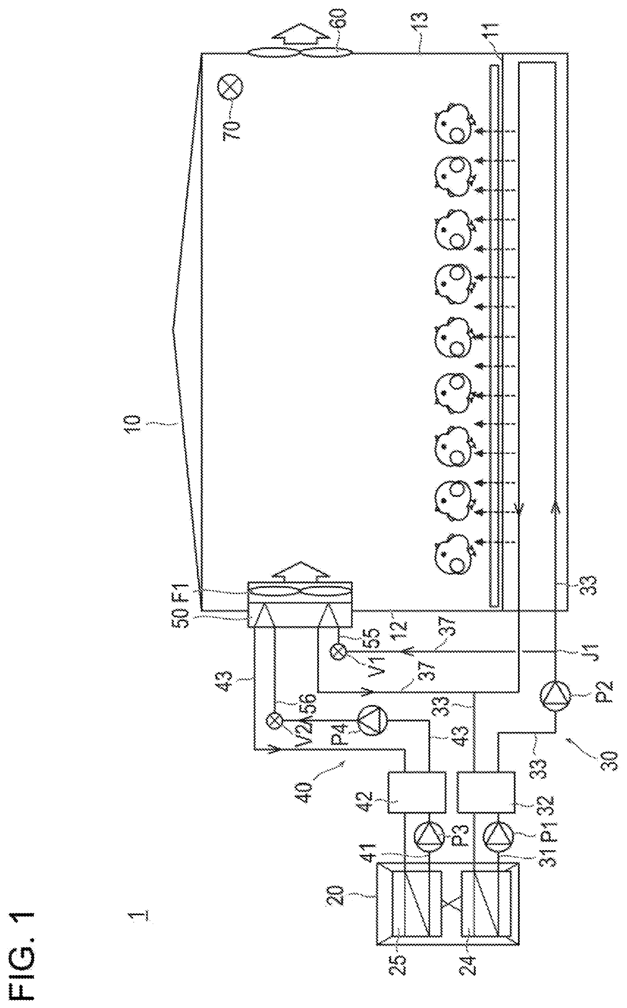
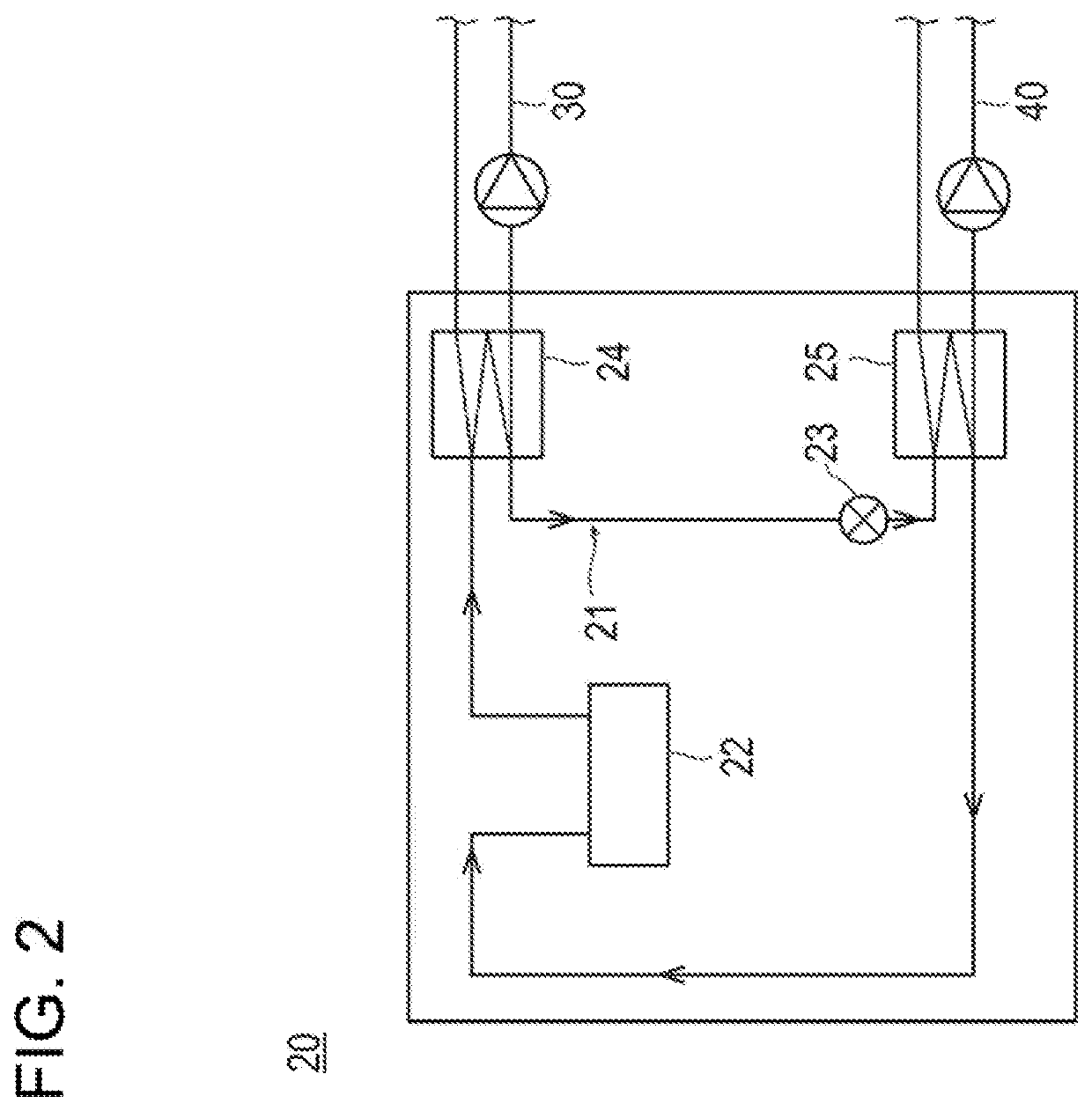
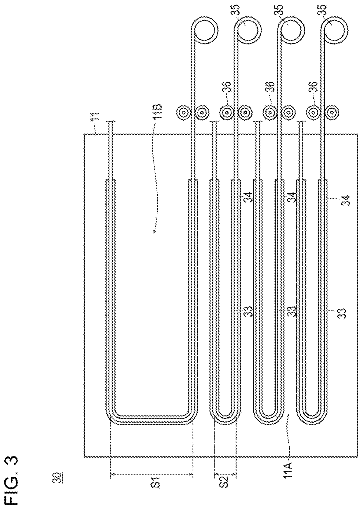
[0022]FIG. 1 is a systematic diagram showing a poultry farming system (livestock stall system) 1 according to a first embodiment. FIG. 2 is a systematic diagram showing a heat pump 20 of the poultry farming system 1 according to the first embodiment. FIG. 3 is a systematic diagram showing a portion of the heating unit 30 of the poultry farming system 1 according to the first embodiment and is a diagram when viewed from above. In FIG. 3, the heating unit 30 is shown by a solid line for eas...

second embodiment

[0072]Next, a poultry farming system 2 according to a second embodiment will be described with reference to FIGS. 4 to 6. FIG. 4 is a systematic diagram showing a poultry farming system 2 according to a second embodiment and is a diagram showing a state when floor heating is performed. FIG. 5 is the systematic diagram showing the poultry farming system 2 according to the second embodiment and is a diagram showing a state when floor cooling is performed. FIG. 6 is the systematic diagram showing the poultry farming system 2 according to the second embodiment and is a diagram showing a state in which a first medium and a second medium are mixed to bring a floor surface 11 of a poultry house 10 to a predetermined temperature. A description of portions common to the first embodiment will be omitted, and portions having features only in the second embodiment will be described. Note that the same members as those in the first embodiment described above are denoted by the same reference num...

modified example 1

[0085]Next, a configuration of a poultry farming system according to Modified Example 1 will be described with reference to FIG. 7. FIG. 7 is a systematic diagram showing a portion of a heating unit 130 of a poultry farming system according to Modified Example 1.

[0086]In the embodiment described above, the positioning portion 34 positions the second pipe 33 such that the intervals S1 and S2 between the adjacent second pipes 33 are different from each other. However, as shown in FIG. 7, the positioning portion 34 may position the second pipe 33 such that the intervals S1 and S2 are variable and a lateral length of the second pipe 33 is partially reduced. At this time, as shown in FIG. 7, a warm place 11A and a cool place 11B are formed on the floor surface 11 of the poultry house 10, and the cool place 11B can be formed in a wider range.


PUM


Abstract

A livestock stall system which can take measures against the cold of winter and against the heat of summer while preventing worsening of the condition of the litter (the flooring) and maintaining a favorable environment inside the livestock stall. This livestock stall system includes a livestock stall in which livestock is raised, and a second pipe which is arranged so as to pass beneath the floor of the livestock stall and which adjusts the temperature of the floor surface of the livestock stall by circulating a medium through the inside of the pipe.

Description

TECHNICAL FIELD[0001]The present invention relates to a livestock stall system.BACKGROUND ART[0002]A livestock stall system is required to maintain a favorable livestock raising environment. For example, a poultry farming system needs to take measures against the cold of winter and the heat of summer to maintain a favorable chicken raising environment. In particular, since newborn chicks are fragile, the newborn chicks need to be kept in a high-temperature close to body temperature and calm environment.[0003]Examples of a method of heating the livestock stall can include hot air heating and brooder heating. The hot air heating is undesirable because irradiating the chicks with wind will take the body temperature away from the chicks. In addition, the brooder heating is undesirable because it uses fossil fuels and generates carbon dioxide, which leads to global environmental degradation. In addition, in a gas brooder method used for heating, since local heating is applied, the temper...

Claims


Application Information

Patent Timeline
Patent Type & Authority Applications(United States)
IPC IPC(8): A01K1/00F24D3/14F24D3/18
CPCA01K1/0011A01K1/0076A01K1/0082F24D3/145F24D3/18A01K1/00Y02B30/00Y02B30/12Y02P60/50Y02A40/70Y02A40/76Y02P60/12
Inventor HIGUCHI, KIYOSHIKITAYAMA, HIDEHIROITO, KAZUTOSHIOKADA, TAKAYUKI
Owner MAYEKAWA MFG CO LTD
Why Eureka
Try Eureka