
Stator for rotary electric machine and method of manufacturing the stator

a technology of rotary electric machines and stator coils, which is applied in the direction of magnets, magnetic circuit shapes/forms/construction, magnetic bodies, etc., can solve the problems of stator coils protruding, electric short circuits, and difficult deformation, and achieve convenient deformation, easy deformation, and convenient deformation.

Active Publication Date: 2011-05-24
DENSO CORP
View PDF12 Cites 7 Cited by
  • Summary
  • Abstract
  • Description
  • Claims
  • Application Information

AI Technical Summary

Benefits of technology

This configuration effectively prevents stator coil protrusion from stator core slots, reducing the risk of electric short circuits and simplifying the manufacturing process by ensuring precise accommodation without additional measurement and confirmation steps.

Problems solved by technology

As disclosed by this publication, in cases where the stator coil is pre-formed and the stator core is combined (assembled) with the pre-formed stator coil, it is considerably difficult to have, with high precision, the stator coil accommodated in the slots of the stator core.
Hence, if the stator coil is left as being protruded, the coil may touch the rotor, whereby there may cause an electric short circuit due to flaking of the coat of the stator coil.
This force will cause the stator coil to deform toward the slot opening, which may also lead to a case that the stator coil protrude, at least partly in height, from some of the slots of the stator core.

Method used


Image

  • Stator for rotary electric machine and method of manufacturing the stator
  • Stator for rotary electric machine and method of manufacturing the stator
  • Stator for rotary electric machine and method of manufacturing the stator

Examples


first embodiment

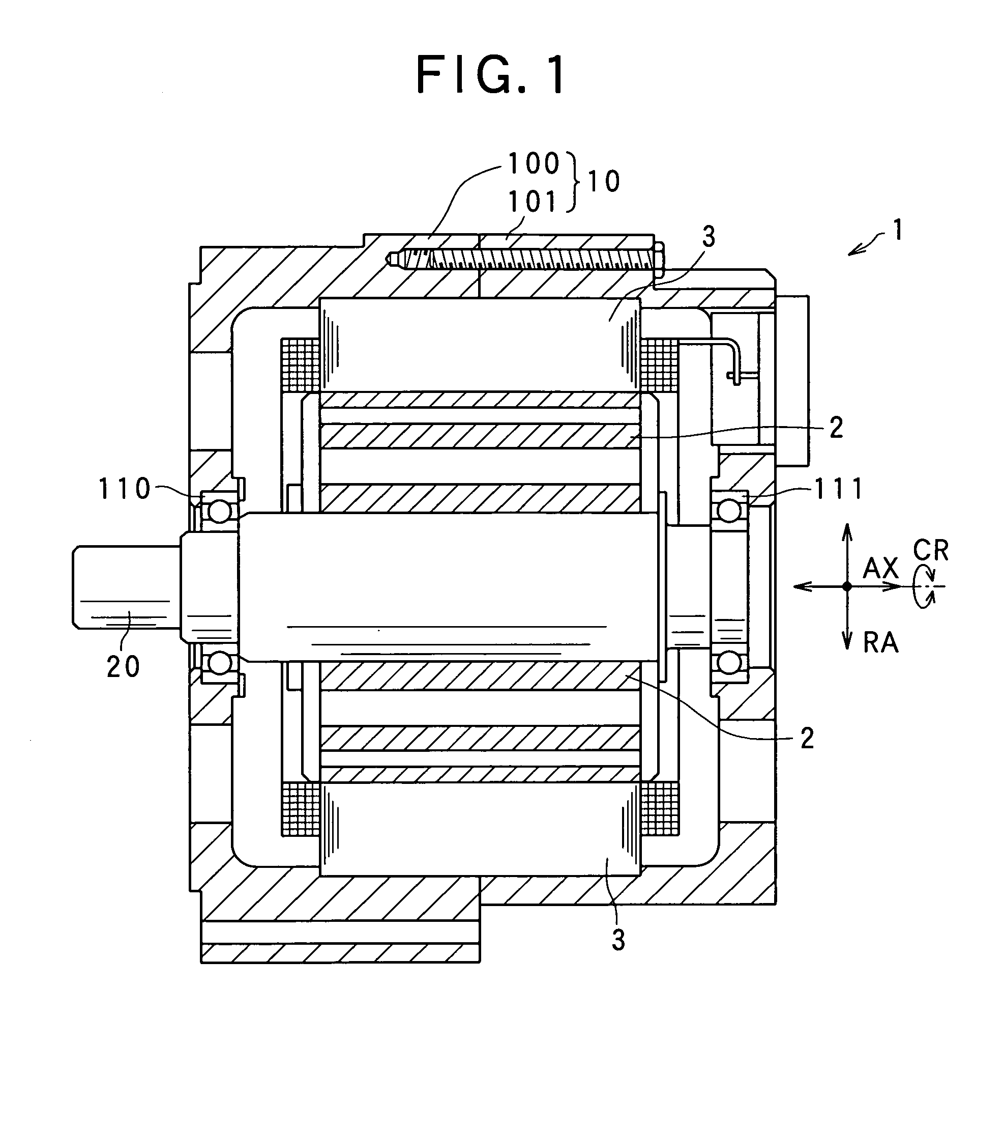
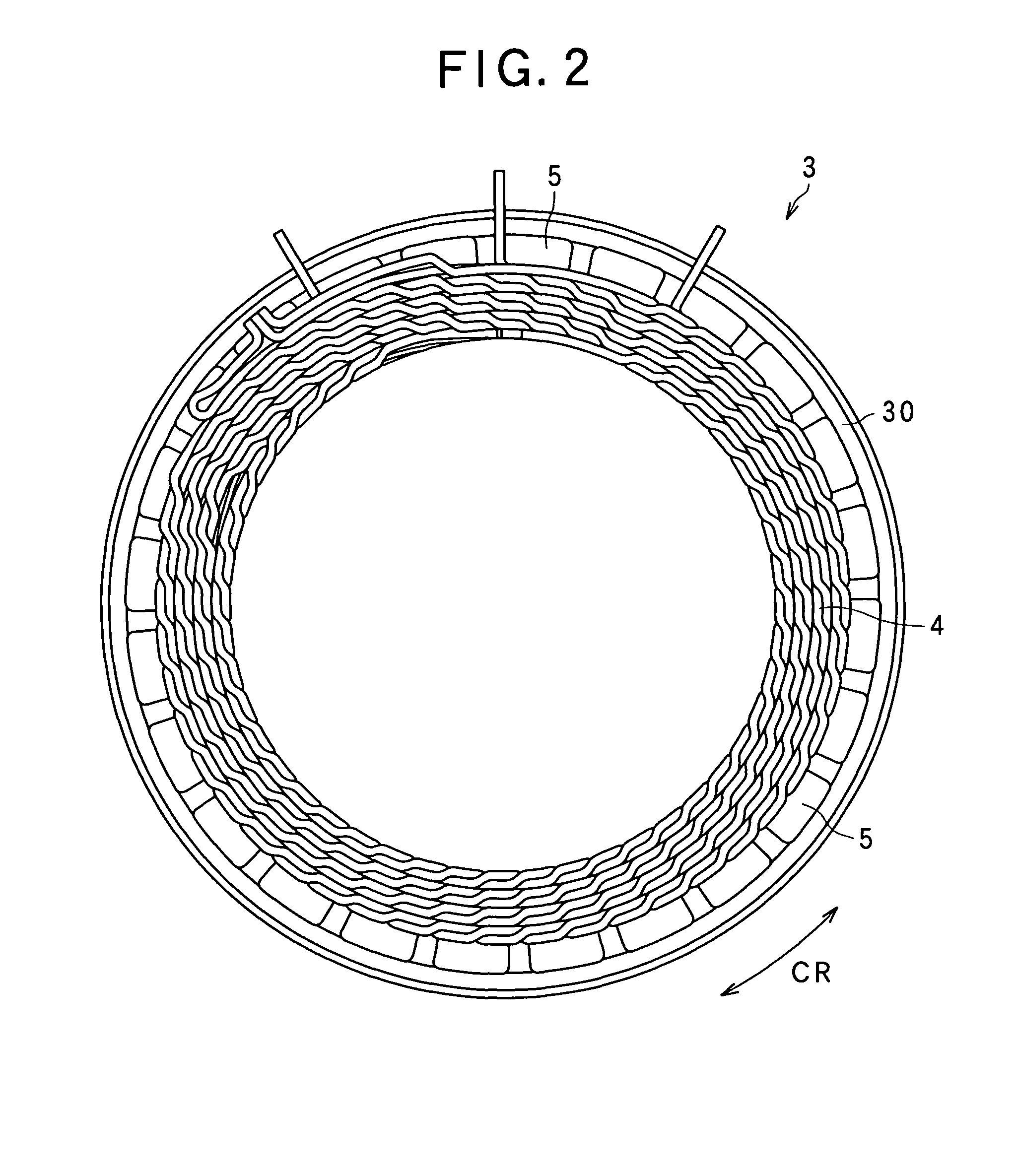
First of all, the configuration of a rotary electric machine which uses the stator of the rotary electric machine according to the present embodiment will now be described. As shown in FIG. 1, this electric machine 1 comprises a housing composed of a pair of housing members 100 and 101 each of which is shaped into an approximately cylindrical shape with a bottom and an opening, wherein the respective openings of both housing members being connected to each other, a rotary shaft 20 rotatably supported by bearings 110 and 111 secured to the housing 10, a rotor 2 secured to the rotary shaft 20, and a stator 3 secured to the housing 10 so that the stator is positioned to enclose the rotor 2 within the housing 10.

In the present embodiment, the longitudinal direction of the rotary shaft 20 is defined as an axial direction(s) AX, the directions radially extending from the rotary shaft 20 along a plane perpendicular to the axial direction AX is defined as a radial direction(s) RA, and the d...

second embodiment

Referring to FIGS. 11A and 11B, a stator 3 according to the second embodiment will now be described. In the present and subsequent embodiments, the components identical or similar to those described in the first embodiment are given the same reference numerals for the sake of simplified or omitted description.

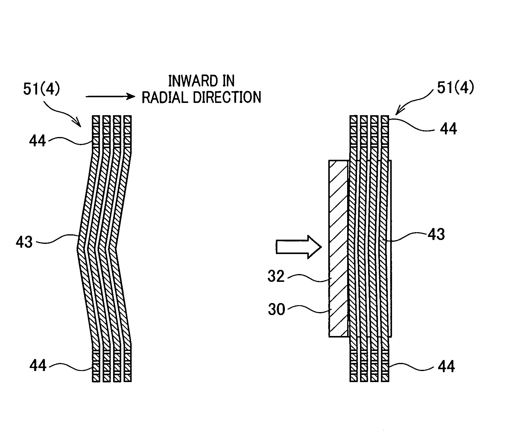
The stator 3 according to the second embodiment differs from that in the previous embodiment in the shape of a stator coil 140 provided in the state prior to being assembled with the stator core 30. As shown in FIG. 11A, where the stator coil 140 provided with slot accommodation portions 143 and coil end portions 44 is provided. Each of the slot accommodation portions 143 has a connection portion integrally formed with one of both coil end portions 44 and the connection portion is formed to have a tangent line which is substantially parallel to the axial line AX of the stator coil 4. In other words, each slot accommodation portion 143 is gradually bent from both axial ends of t...

third embodiment

Referring to FIGS. 12A and 12B, a stator 3 according to the third embodiment will now be described.

The stator 3 according to the third embodiment differs from that in the previous embodiments in the shape of a stator coil 240 provided in the state prior to being assembled with the stator core 30. The stator coils 4 and 140 explained in the first and second embodiments are given the axial central parts each having a pointed top. In contrast, in the present embodiment, as shown in FIG. 12A, a stator coil 240 has stator coils 240 given slot accommodation portions 243 and each of the slot accommodation portions 243 is bent in the same way as the foregoing, but to have a smoothly bent round top. That is, the whole segment of each of the slot accommodation portions 243 is curved. As a result, as shown in FIG. 12B, when the slot-accommodated portions 243 are pressed by the stator core 30, a substantial area contact can be achieved between the stator core 30 and the slot-accommodated portio...


PUM

PropertyMeasurementUnit
thicknessaaaaaaaaaa
thicknessaaaaaaaaaa
thicknessaaaaaaaaaa

Abstract

A rotor provided in rotary electric machines comprises a stator core having a radial direction and slots provided with bottomed openings directed in the radial direction. The rotor also comprises a stator coil comprising slot accommodation portions being accommodated in the slots of the stator core and coil end portions each connecting mutually adjacent slot accommodation portions among the slot accommodation portions and respectively protruding from both end faces of the stator core. The stator coil is pre-formed into a cylindrical shape before the slot accommodation portions are accommodated into the slots of the stator core. The slot accommodation portions are formed to respectively have convex parts each protruding toward an opposite way to the slot openings, before the slot accommodation portions are accommodated into the slots. The convex parts are pressed by the stator core toward the openings during accommodation of the slot accommodation portions into the slots.

Description

CROSS-REFERENCE TO RELATED APPLICATIONThis application is based on and claims the benefit of priority from earlier Japanese Patent Application No. 2008-113650 filed on Apr. 24, 2008, the description of which is incorporated herein by reference.BACKGROUND OF THE INVENTION1. Technical Field of the InventionThe present invention relates to a stator for rotary electric machines and a method of manufacturing the stator.2. Related ArtIn recent years, rotary electric machines used for electric motors and electric generators are required to be compact in size, to be able to output higher power, and to be of higher quality. In particular, when a rotary electric machine is mounted on a vehicle, the space in which the rotary electric machine is accommodated has become smaller, while it is demanded that the output therefrom is higher. In this circumstance, the conventional rotary electric machine has been provided by the structure for a stator whose stator coil is composed of a continuous windi...

Claims


Application Information

Patent Timeline
Patent Type & Authority Patents(United States)
IPC IPC(8): H02K3/48H02K15/06H02K3/46
CPCH02K3/12H02K3/48H02K15/0421H02K15/066H02K15/0081H02K1/16Y10T29/49009Y10T29/49073H02K15/0478
Inventor DOBASHI, MASAOMIAKIMOTO, AKITOYANAGISAWA, YOSHINOBU
Owner DENSO CORP
Learn More