Cargo carrier

a cargo carrier and carrier technology, applied in the field of cargo carriers, can solve the problems of complicated adjustment or elevating systems, cumbersome and difficult to achieve, and limited ground clearance of such vehicles, so as to facilitate loading and unloading

Inactive Publication Date: 2011-05-31
ABSOLUTE ELECTRONICS SOLUTIONS
View PDF174 Cites 54 Cited by
  • Summary
  • Abstract
  • Description
  • Claims
  • Application Information

AI Technical Summary

Benefits of technology

[0012]Therefore, the present invention provides a cargo carrier that has a frame for supporting articles thereon with the frame being raisable and lowerable and tiltable relative to the wheels and tires and support surface or ground via pivotal movement of support arms that extend from the frame and have respective wheels and tires mounted thereon. The cargo carrier thus may be readily adjusted via pivotal movement of the support arms to set the frame (and a deck mounted thereon) at a desired height or tilt angle to ease loading and unloading of the cargo carrier. The wheels and tires are rotatably mounted to the separate respective support arms such that corresponding wheels on opposite sides of the cargo carrier do not have an axle extending therebetween. The support arms and associated actuators function to adjust the height and tilt angle of the frame and also function as a suspension system for the cargo carrier.

Problems solved by technology

Also, although such vehicles are often capable of transporting and elevating cargo to a desired elevated loading area, such as at an aircraft or the like, the cargo or articles must first be lifted upward onto the vehicle platform, which is often cumbersome and difficult to accomplish, and sometimes requires a forklift or the like.
The ground clearance of such vehicles is limited by the size of the wheels and tires.
Such systems are complicated adjustment or elevating systems and do not allow for adjustment of the ground clearance of the trailer or vehicle or allow for the vehicle to travel over uneven terrain.

Method used


Image

  • Cargo carrier
  • Cargo carrier
  • Cargo carrier

Examples


Embodiment Construction

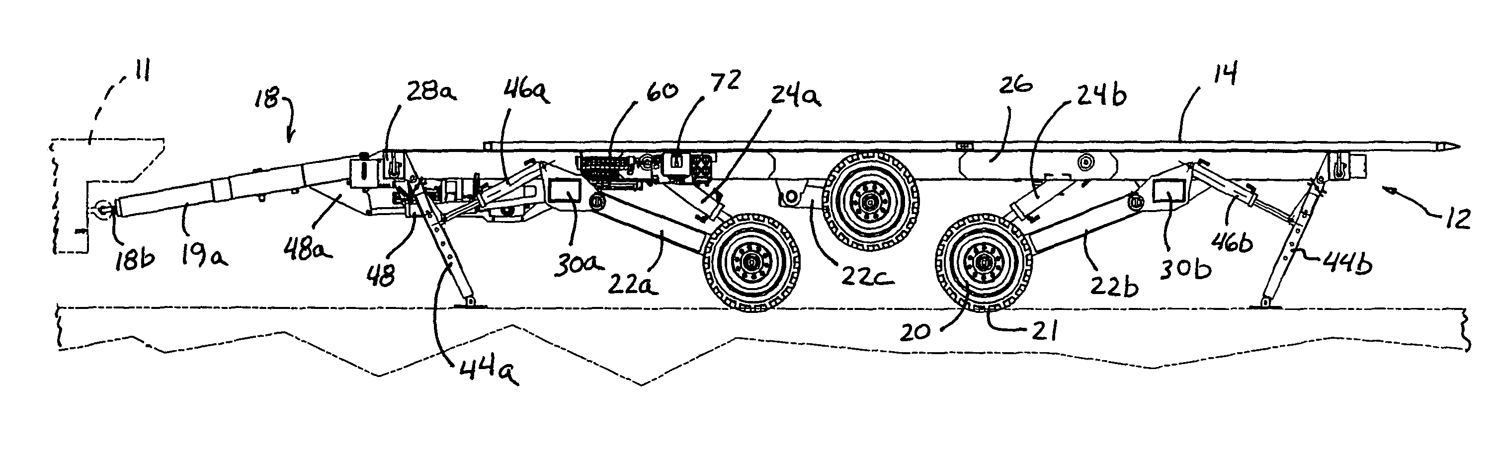
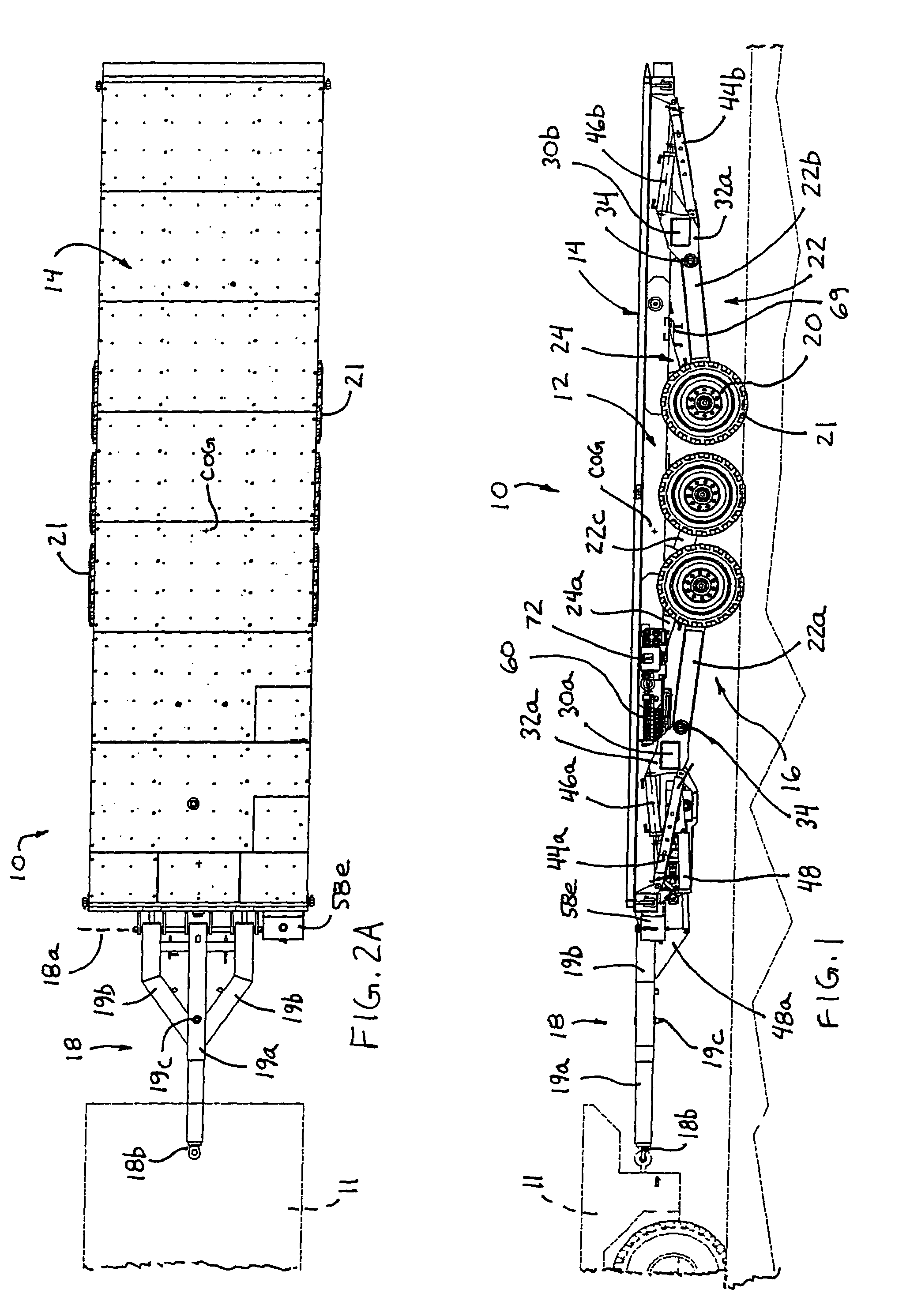
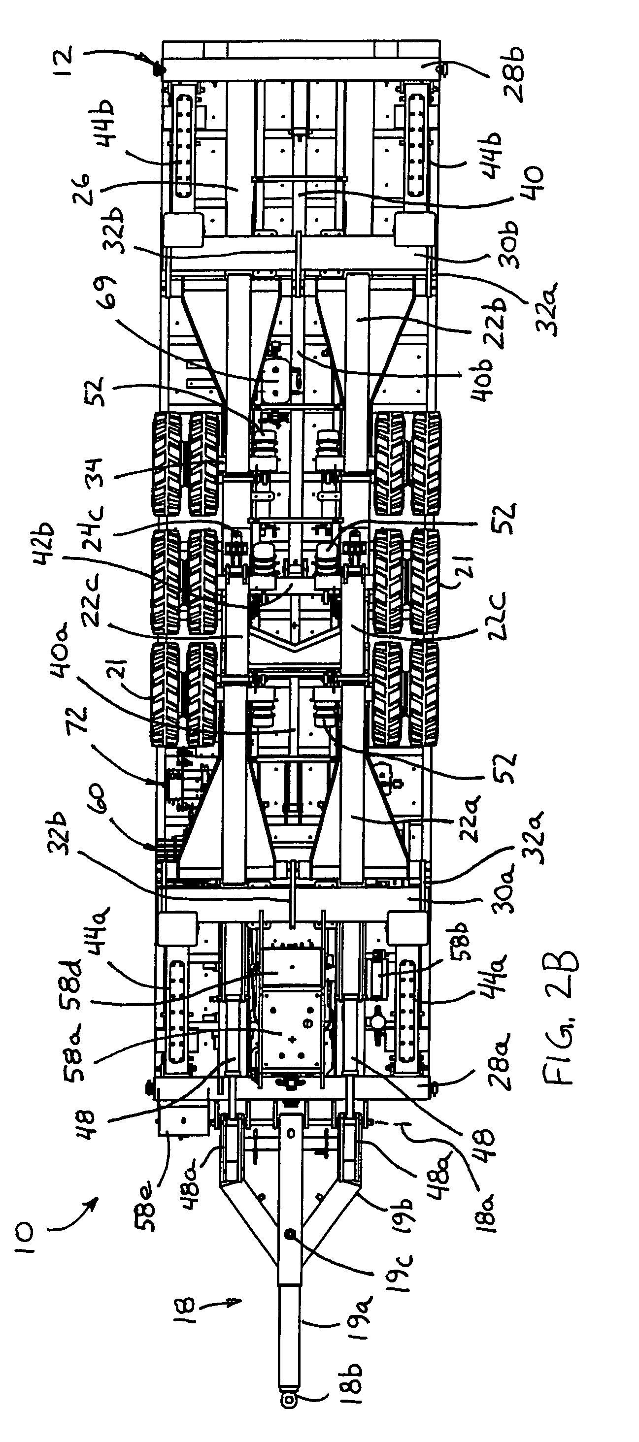
[0048]Referring now to the drawings and the illustrative embodiments depicted therein, a cargo carrier or cargo trailer 10 includes a frame or frame portion 12 and a deck or deck portion 14 mounted to the frame 12, which is supported by a support system 16 (FIGS. 1-15). Cargo carrier 10 is connectable to a tow vehicle 11 via a draw bar or tow bar or arm 18 at a forward end of the cargo carrier. Support system 16 includes wheels 20 and tires 21 rotatably mounted to support arms or members or elements 22, which are adjustably or pivotably mounted to frame 12. Each wheel 20 and tire 21 (or two wheels and tires in tandem as can be seen in FIGS. 3 and 13) is / are rotatably mounted to a respective support arm 22, such that no axle extends between the corresponding support arms and wheels at respective arms at opposite sides of the cargo carrier. Thus, the cargo carrier 10 may provide increased ground clearance and enhanced handling capabilities of uneven terrain. Support system 16 includes...


PUM


Abstract

A cargo carrier for movably supporting cargo includes a frame configured to support cargo at the cargo carrier and at least two wheels at each side of the frame. Each of the wheels is rotatably mounted to a respective support arm. The support arms are pivotally mounted to respective sides of the frame and are pivotable relative to the frame to adjust at least one of a height and tilt of the frame relative to a support surface. The cargo carrier is readily adapted to position the frame at a lower position for road applications and a raised position for uneven terrain applications. The cargo carrier may include a deck that is movably mounted to the frame and is longitudinally movable along the frame.

Description

CROSS REFERENCE TO RELATED APPLICATION[0001]The present application claims benefit of U.S. provisional application Ser. No. 60 / 680,559, filed May 13, 2005, which is hereby incorporated herein by reference in its entirety.FIELD OF THE INVENTION[0002]The present invention relates generally to a vehicle or trailer for carrying cargo and, more particularly, to a trailer or truck or other vehicle that may carry cargo on a deck of the trailer or truck or vehicle that is adjustable relative to the wheels and tires of the trailer or truck or vehicle.BACKGROUND OF THE INVENTION[0003]Vehicles for carrying cargo and for loading cargo into vehicles, such as aircraft and the like, are generally known. Such vehicles typically have a platform that may be raised upward to position the platform at a loading portion of the vehicle or aircraft to ease loading of the cargo from the vehicle to the aircraft. The vehicles may be able to adjust the platform to maintain the platform relatively level at the ...

Claims


Application Information

Patent Timeline
Patent Type & Authority Patents(United States)
IPC IPC(8): B60P1/00B60G17/00
CPCB60G17/02B60P1/027B60G2204/47B60G2300/38B60G2500/30B60G2300/04
Inventor QUENZI, PHILIP JJENNEY, RICHARD W
Owner ABSOLUTE ELECTRONICS SOLUTIONS
Why Eureka
Try Eureka