
Medical shunt/valve for regulation of bodily fluids

a technology of bodily fluids and shunts, which is applied in the direction of valves, wound drains, intravenous devices, etc., can solve the problems of serious neurological problems, potential death, and fluid production rate imbalance,

Active Publication Date: 2011-05-31
WISCONSIN ALUMNI RES FOUND
View PDF35 Cites 2 Cited by
  • Summary
  • Abstract
  • Description
  • Claims
  • Application Information

AI Technical Summary

Benefits of technology

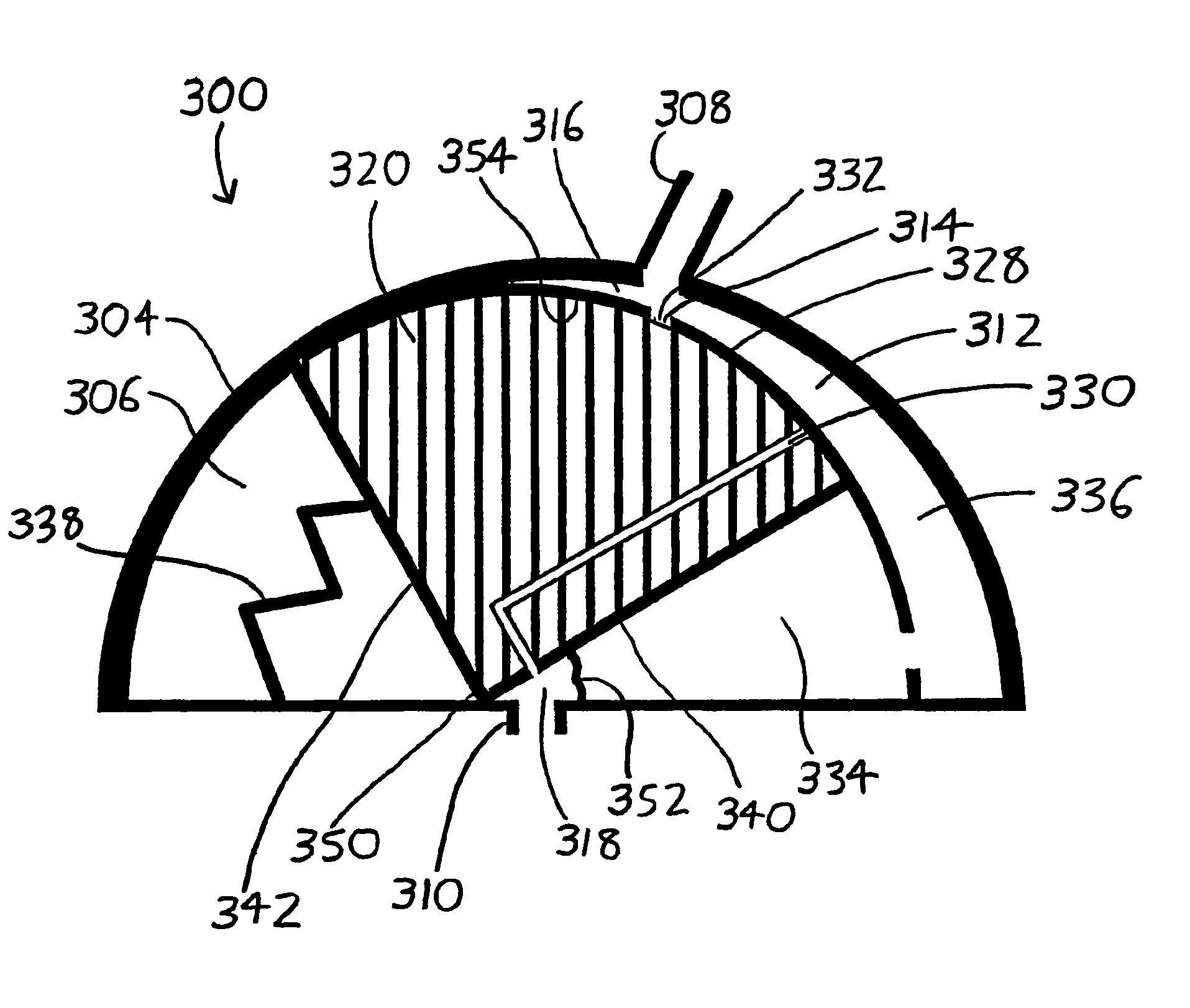
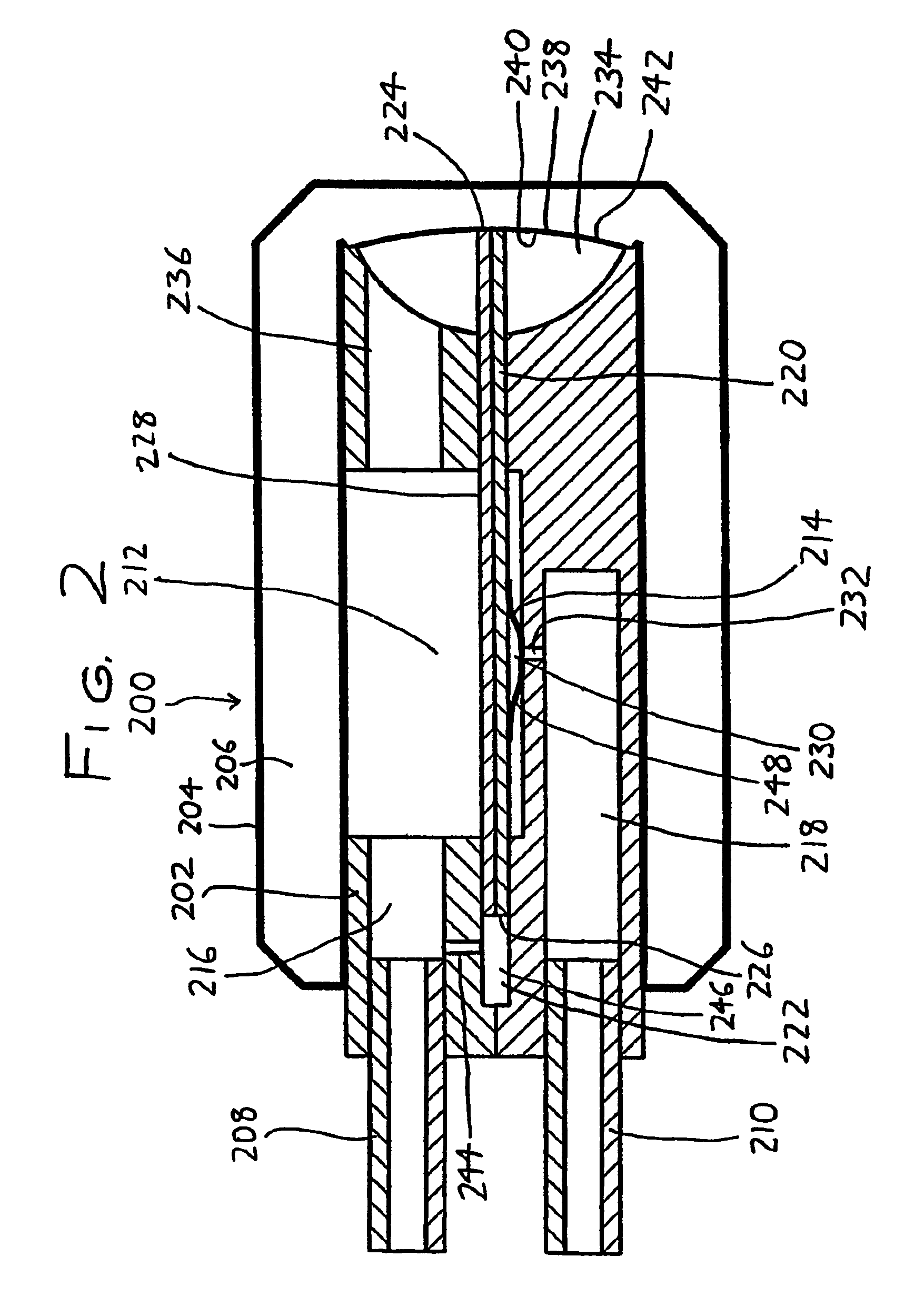
The invention is a shunt for maintaining proper pressure of cerebrospinal or other body fluids. It includes an inlet, an outlet, and a fluid passage between them. A valve is situated between the inlet and outlet ports, with a movable valve actuating member that will open or close the valve based on the pressure on the upstream side of the fluid passage. The valve actuating member is biased towards the closed state but will open when the pressure on the upstream side exceeds the closing force. The valve is designed to open only when there is a significant pressure on the upstream side, preventing siphoning when pressure on the downstream side drops. The valve actuating member may be a displaceable piston or a flexible mask, and the closing force may be provided by an elastic diaphragm or a mechanical spring. The invention solves the problem of excessive siphoning and provides a more effective and reliable shunt for maintaining proper fluid pressure.

Problems solved by technology

However, in some cases an imbalance occurs between the rate of fluid production and the rate of reabsorption.
This can lead to serious neurological problems, and potentially death.
Common shunts are subject to numerous problems which designers have long sought to overcome, such as problems with tissue ingrowth and fouling, plaque buildup, and size and cost issues.
Control of shunt valve response characteristics (i.e., flow volume vs. pressure characteristics) remains a major issue, with common problems being that response characteristics may undesirably change over time, and it is often difficult to easily adjust the response characteristics of a shunt to suit the needs of individual patients.
Another common problem is the tendency for a shunt valve to open once a static threshold pressure difference is present, but then remain partially open after this static pressure difference is relieved.
This effect arises owing to the dynamic pressure of fluid flow, and can (for example) result in unnecessary drainage at of cerebrospinal fluid at lower than desired pressures in the ventricles.
Another disadvantage of many shunts is that they operate in the manner of a common check valve, wherein their flow is dependent on the pressure difference across the valve between its inlet and outlet.
This arrangement can lead to the problem of siphoning: since opening of the valve is in part dependent on the pressure at the valve outlet, low pressure on the outlet side may cause the valve to open even if the pressure on the inlet side is not indicative of excess cerebrospinal fluid pressure in the ventricles.
Thus, if a patient repositions his / her head with respect to the rest of his / her body—for example, by standing up from a supine positiondecreased pressure in the peritoneal cavity can increase the pressure difference to such an extent that the valve opens and unnecessarily drains cerebrospinal fluid.
A further disadvantage of many shunts is that they allow reversible flow, i.e., they can allow backflow from the peritoneal cavity to the brain if the (downstream) pressure in the peritoneal cavity should for some reason exceed the (upstream) pressure in the brain by the same threshold pressure difference (though in this case the pressure difference is reversed between the upstream and downstream sides).
This is naturally undesirable since it can cause a sudden increase in fluid pressure on the brain, whereas a sudden increase in fluid pressure in the peritoneal cavity is generally not critical.

Method used


Image

  • Medical shunt/valve for regulation of bodily fluids
  • Medical shunt/valve for regulation of bodily fluids
  • Medical shunt/valve for regulation of bodily fluids

Examples


Embodiment Construction

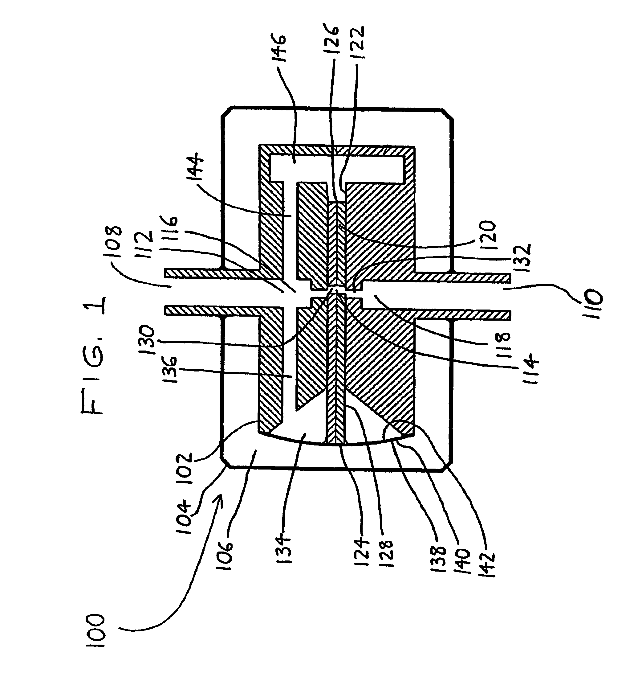
[0017]Several preferred versions of the invention will now be reviewed. Initially referring to FIG. 1, a first basic version of a shunt is depicted generally by the reference numeral 100. The shunt 100 includes an inner body 102 separated from an outer casing 104 by a gas chamber 106, with the inner body 102 being supported within the outer casing 104 by an inlet port 108 and an outlet port 110. The inlet port 108 protrudes from the outer casing 104, and may be connected to an inlet catheter (not shown) leading the ventricles of a brain. The outlet port 110 similarly protrudes from the outer casing 104, and may be connected to an outlet catheter leading to the peritoneal cavity or some other site for receiving cerebrospinal fluid.

[0018]A fluid passage 112 extends between the inlet port 108 and outlet port 110 to allow flow of cerebrospinal fluid therebetween. However, such flow is not unregulated; a valve 114 (i.e., an openable and closable gate) opens and closes the fluid passage 1...


PUM


Abstract

Shunts (valves) (100) for controlled flow of bodily fluids, such as cerebrospinal fluid, include a valve actuating member (114) (such as a piston (120)) between inlet (108) and outlet (110) ports. The valve actuating member is biased toward a state wherein the valve is closed, and it includes a face adjacent the upstream side of the valve (and preferably isolated from the downstream side of the valve) whereby fluid pressure in the upstream side exerts an opening force on the face to urge the valve toward an open state. When the opening force on the valve exceeds the closing force by some amount, the valve actuating member moves the valve to the open state, allowing fluid flow through the fluid passage between the inlet and outlet ports.

Description

CROSS-REFERENCE TO RELATED APPLICATIONS[0001]This application claims priority under 35 USC §119(e) to U.S. Provisional Patent Application 60 / 501,358 filed 9 Sep. 2003, the entirety of which is incorporated by reference herein.FIELD OF THE INVENTION[0002]This document concerns an invention relating generally to medical shunts for controlling the flow of body fluids, e.g., shunts for drainage of cerebrospinal fluid for treatment of hydrocephalus and similar conditions.BACKGROUND OF THE INVENTION[0003]Numerous physiological processes rely on a proper balance between generation and disposal of bodily fluids. As an example, within the body, the brain and spinal cord are bathed in cerebrospinal fluid, which helps maintain their proper operation. Large cavities within the brain, the ventricles, produce and reabsorb the cerebrospinal fluid so that it is regularly replaced for healthy operation of the body's neurological system. However, in some cases an imbalance occurs between the rate of ...

Claims


Application Information

Patent Timeline
Patent Type & Authority Patents(United States)
IPC IPC(8): A61M5/00A61MA61M39/22
CPCA61M39/22A61M27/006
Inventor MEDOW, JOSHUA E.LUZZIO, CHRISTOPHER C.
Owner WISCONSIN ALUMNI RES FOUND
Learn More