
Liquid chamber cap with compartment for use with injectables

a technology of liquid chamber and injectable, which is applied in the field of liquid and/or dry ingredient dispensing caps, can solve the problems of reducing the shelf life after mixing, reducing the effective strength, and reducing the stability of pharmaceuticals and other substances, and achieves the effect of convenient maneuverability

Active Publication Date: 2011-05-31
BLAST MAX
View PDF11 Cites 21 Cited by
  • Summary
  • Abstract
  • Description
  • Claims
  • Application Information

AI Technical Summary

Benefits of technology

"The present invention is a cap for a bottle, pouch, or receptacle that houses a syringe injectable liquid. The cap has a storage chamber for a substance to be mixed with the liquid and consumed through a straw or directly from the receptacle. The cap can be used with a syringe or a drinking straw. The cap has a sleeve penetrator that acts as a reciprocal member and can be manually moved downwardly to dispense the substance in the cap body into the syringe or other container. The cap can be sealed to protect the contents from contamination. The technical effects of this invention include improved mixing of substances and easier consumption of the mixed contents."

Problems solved by technology

Many pharmaceuticals and other substances do not retain their stability, strength and effectiveness for long after the ingredients have been mixed in solution or suspension with a different liquid.
This reduced shelf life after mixing mandates that the mixed product be utilized relatively soon after mixture to obtain full strength to prevent loss of effective strength, deterioration, discoloration, interactions and reduced effectiveness.
Certain drugs begin to lose their effectiveness when mixed together and thus have a short shelf life.

Method used


Image

  • Liquid chamber cap with compartment for use with injectables
  • Liquid chamber cap with compartment for use with injectables
  • Liquid chamber cap with compartment for use with injectables

Examples


Embodiment Construction

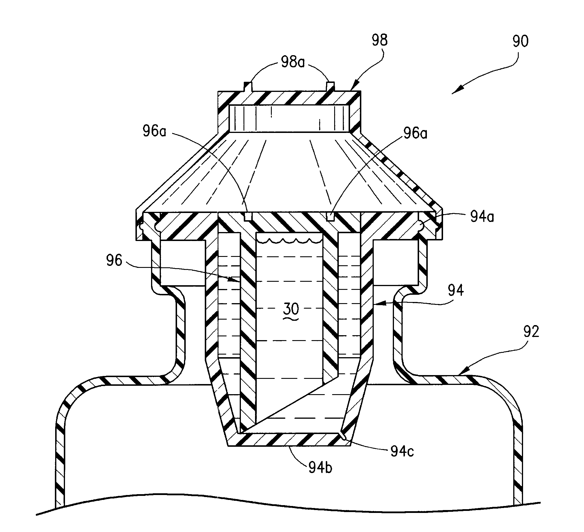
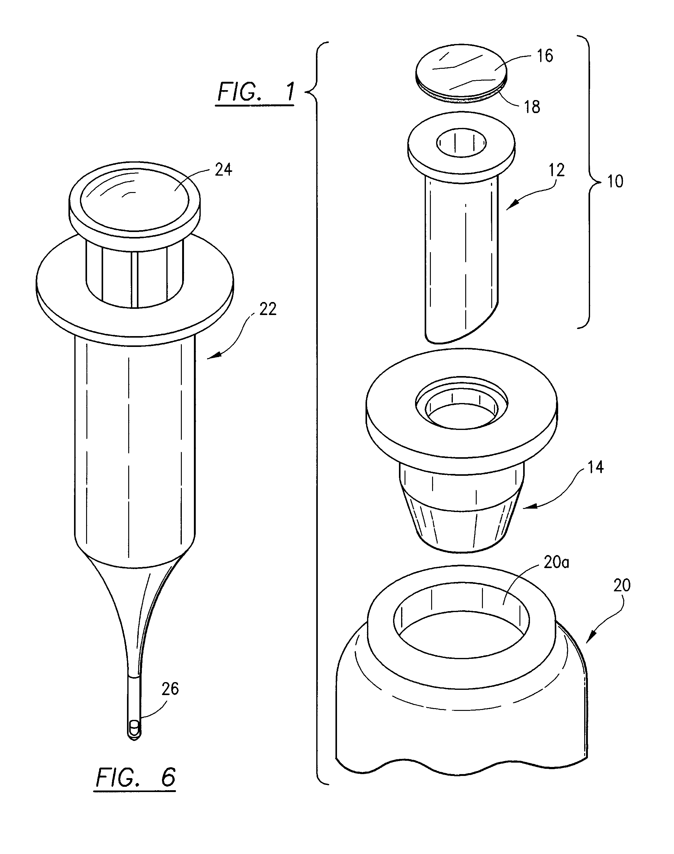
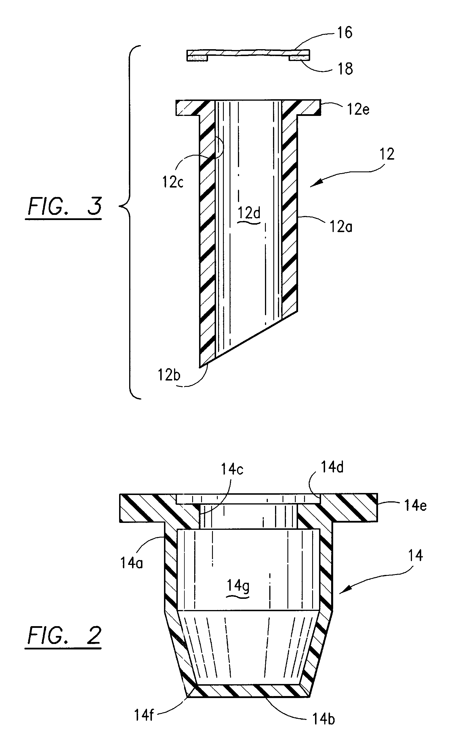
[0029]Referring now to FIG. 1, an injectable container cap 10 is shown comprised of a molded plastic cap body 14, a sleeve penetrator 12 and sealable cover 16 positioned above an injectable substance container 20 having a container neck opening 20a.

[0030]The sleeve penetrator 12 is a rigid plastic cylinder that is hollow and has a central passage there through. The lower end of the sleeve penetrator 12 is cut at an oblique angle to the longitudinal axis which allows the lower end or base of sleeve penetrator 12 to penetrate through the bottom floor of cap body 14 as described below.

[0031]A sealable disc-shaped protective cover 16 has adhesive 18 coated on certain portions on the cover 16 bottom, which allows the cover 16 to be adhesively attached and sealed to the top lip of sleeve penetrator 12. The cover 16 could be made of metal, foil, plastic, rubber or a rubber like material formed as a plug through which a needle can penetrate.

[0032]One purpose of the invention is to allow so...


PUM


Abstract

A storage and dispensing cap for a liquid receptacle having a cap body storage chamber for use with a receptacle such as a bottle, pouch or intravenous bag that is used to store a liquid for use with a syringe that is inserted into the receptacle for drawing the liquid contents into the syringe. A liquid, powder or capsule in the cap body chamber is mixed into the liquid receptacle for use with the syringe. A sleeve penetrator is mounted inside said cap body chamber and is sized in length to permit rupture of the bottom floor of said cap body chamber when manually depressed for dispensing whatever material is placed inside said cap body chamber and sleeve penetrator into said syringe bottle. An open passage from the cap body to the inside of the receptacle is provided once the storage chamber is ruptured by manually depressing the penetrator to allow the syringe needle end to be inserted into the liquid receptacle.

Description

BACKGROUND OF THE INVENTION[0001]1. Field of the Invention[0002]A liquid and / or dry ingredient dispensing cap that can be mounted to a pharmaceutical substance container or receptacle such as a bottle, pouch, syringe test tube or any container that can hold a liquid for storing injectable pharmaceuticals or any other ingredients used for injection into a human being.[0003]2. Description of Related Art[0004]Many pharmaceuticals and other substances do not retain their stability, strength and effectiveness for long after the ingredients have been mixed in solution or suspension with a different liquid. This reduced shelf life after mixing mandates that the mixed product be utilized relatively soon after mixture to obtain full strength to prevent loss of effective strength, deterioration, discoloration, interactions and reduced effectiveness. The process of loss of chemical effectiveness is often termed “shelf life.” Once two different chemicals are combined, the process of deteriorati...

Claims


Application Information

Patent Timeline
Patent Type & Authority Patents(United States)
IPC IPC(8): A61M39/20B65D39/00
CPCA61J1/1412A61J1/18A61J1/2096A61J1/2093A61J1/10A61J2001/2027A61J2001/1468A61J1/1468A61J1/2027B01L3/523B01L2300/042B01L2300/044B01L2300/0672
Inventor ANDERSON
Owner BLAST MAX
Learn More