Head stack assembly with suspension supporting head slider and hard disc drive including the same

a technology of suspension support and head slider, which is applied in the direction of head, record information storage, instruments, etc., can solve the problems of magnetic head deviating laterally from a specified track, not suppressing the tendency of the magnetic head to run off track, and affecting the effect of magnetic head movemen

Inactive Publication Date: 2011-05-31
SAMSUNG ELECTRONICS CO LTD
View PDF9 Cites 7 Cited by
  • Summary
  • Abstract
  • Description
  • Claims
  • Application Information

AI Technical Summary

Benefits of technology

[0009]An object of the present invention is to provide a head stack assembly (HSA) which minimizes the extent to which the magnetic head runs off-track due to disk vibration and due to suspension bending.
[0010]Likewise, another object of the present invention is to provide a hard disk drive (HDD) whose magnetic head will hardly run off-track when vibrations are induced in the HDD.
[0011]Another object of the present invention is to provide a hard disk drive (HDD) that can process data at high speeds.
[0012]Still another object of the present invention is to provide an HDD that can function well with a disk having a high number of tracks per inch (TPI).

Problems solved by technology

However, the magnetic head may deviate laterally from a specified track due to vibrations in the disk or the HSA.
Such vibrations may be created when the HDD is disturbed or when the spindle motor of the HSA is running.
However, the HSAs disclosed in the prior art can not suppress the tendency of the magnetic head to run off-track when vibrations transmitted to the suspension cause the suspension to bend up and down.

Method used


Image

  • Head stack assembly with suspension supporting head slider and hard disc drive including the same
  • Head stack assembly with suspension supporting head slider and hard disc drive including the same
  • Head stack assembly with suspension supporting head slider and hard disc drive including the same

Examples


Embodiment Construction

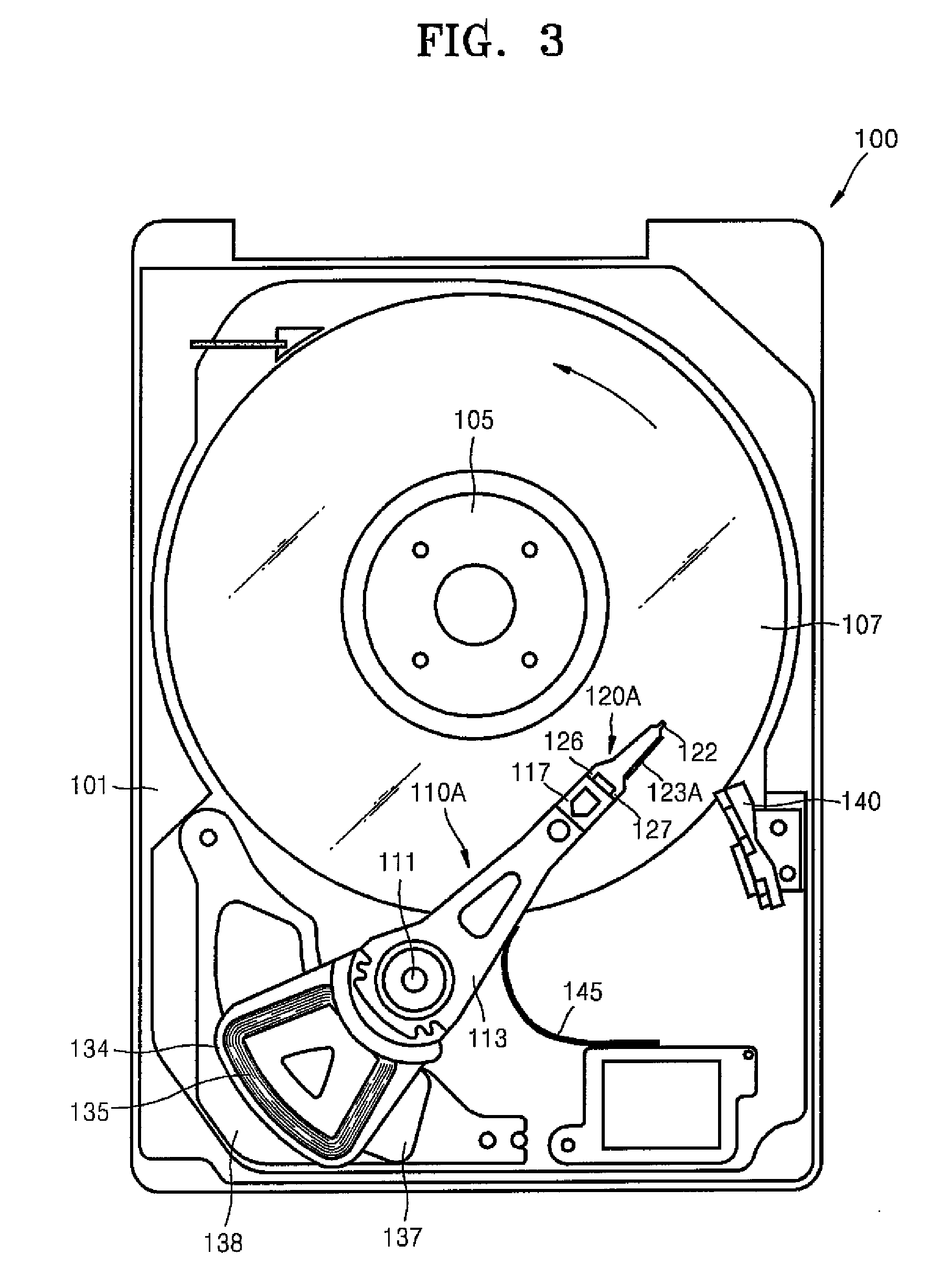
[0027]Referring to FIGS. 3 and 4, an HDD 100 according to the present invention includes a base 101, a spindle motor 105, a data storage disk 107, and an HSA 110A. Also, a cover (not shown) is coupled to the base 101 to form a housing in which the spindle motor 105, disk 107, and HSA 110A are enclosed. The spindle motor is fixed to the base 101 within the housing. The data storage disk 107 is mounted to the spindle motor 105 such that the spindle motor 105 rotates the disk 107 at a high speed in the direction of the arrow in FIG. 3. The HDD 100 also includes a main printed circuit board (PCB, not shown) disposed below the base 101, and a flexible printed circuit (FPC) 145 which electrically connects the HSA 110A to the main PCB.

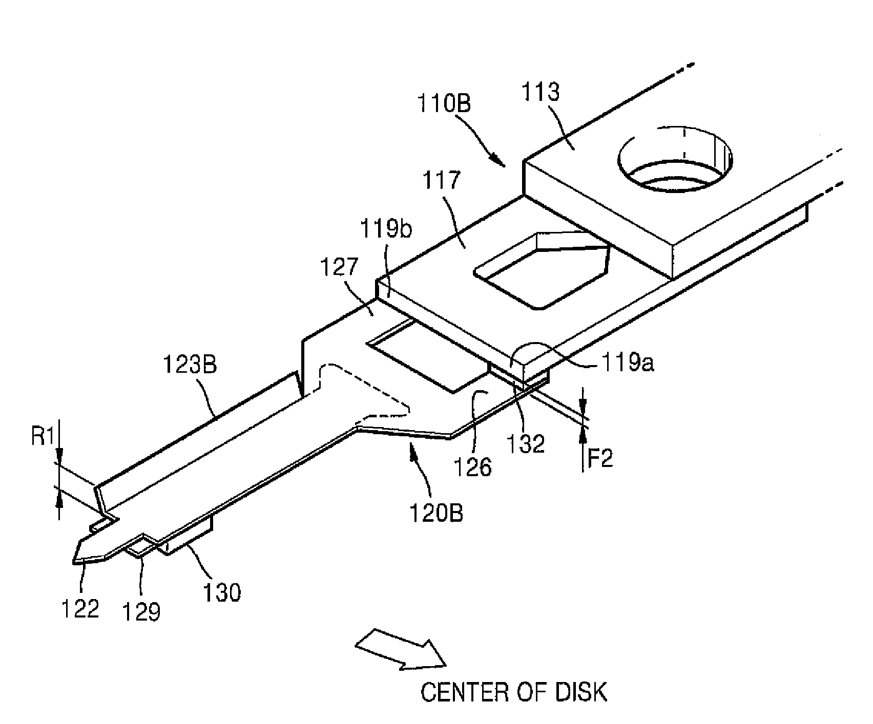
[0028]The HSA 110A includes a head slider 130 having an embedded magnetic head for reading / writing data. The head slider 130 is positioned over a specific track of the disk 107 to read or write data from or onto the disk 107. To this end, the HSA 110A also in...


PUM

PropertyMeasurementUnit
distance F1aaaaaaaaaa
thicknessaaaaaaaaaa

Abstract

A head stack assembly (HAS) of a hard disk drive (HDD) includes a swing arm, a connection plate integral with a terminal end of the swing arm, a head slider including a magnetic head for reading / writing data from / onto a disk, and a suspension that is attached to the connection plate, supports the head slider, and has characteristics which minimize the degree to which the magnetic head will run off-track due to vibrations induced in the HDD. The suspension includes two connecting parts having upper surfaces at which the suspension is attached to the connection plate. In the HDD, the upper surface of the connecting part positioned closest to the center of the disk center lies in a plane beneath the plane in which the upper surface of the other connecting part lies. Also, that half of the suspension which is disposed to one side of the central longitudinal axis of the HSA and is located remotely from the center of the disk in the HDD is stiffer than the other half of the suspension which is proximal the center of the disk. To this end, the suspension includes at least one side-rail that renders the suspension asymmetrical.

Description

BACKGROUND OF THE INVENTION[0001]1. Field of the Invention[0002]The present invention relates to a hard disk drive (HDD). More particularly, the present invention relates to a head stack assembly (HSA) of an HDD.[0003]2. Description of the Related Art[0004]A hard disk drive (HDD) is a device used in personal computers (PCs), MP3 players, mobile phones, and the like to store and retrieve data. To this end, an HDD includes a data storage disk, a spindle motor for rotating the disk, and a magnetic head that reads and writes data from and onto the disk. The head is embedded in a head slider, and when the HDD is operating, the head slider floats a predetermined distance above the disk while the disk is rotated by the spindle motor. The head slider is part of a head stack assembly (HSA) which is controlled to move the magnetic head over specified tracks of the disk. The tracks extend along concentric circles, respectively, whose centers coincide with the center of the disk.[0005]The HSA a...

Claims


Application Information

Patent Timeline
Patent Type & Authority Patents(United States)
IPC IPC(8): G11B5/53G11B21/16
CPCG11B5/4833G11B5/5569G11B5/4886G11B21/02G11B21/10G11B21/21
Inventor LEE, HAENG-SOOKIM, WOO-SUNGOH, DONG-HO
Owner SAMSUNG ELECTRONICS CO LTD
Why Eureka
Try Eureka