Control apparatus for vehicular drive system

a control apparatus and vehicular drive technology, applied in the direction of dynamo-electric gear control, gear control, instruments, etc., can solve the problems of excessive high speed rotation, reduced torque capacity of input clutch, and reduced torque capacity of coupling device, so as to reduce the amount of supply

Inactive Publication Date: 2011-05-31
TOYOTA JIDOSHA KK
View PDF17 Cites 17 Cited by
  • Summary
  • Abstract
  • Description
  • Claims
  • Application Information

AI Technical Summary

Benefits of technology

[0011]The control apparatus constructed according to the above-described mode (1) of the invention, which is configured to limit the output of the engine according to the difference between the actual rotating speed of the mechanical power transmitting portion and the above-indicated theoretical rotating speed, is effective to reduce or prevent an excessive rise of the rotating speed of a rotary member of the mechanical power transmitting portion disposed on one side of a coupling device nearer to the engine, and excessive rises of the rotating speeds of a bearing rotated with the rotary member and an electric motor connected to the rotary member, even in the event of reduction of torque capacity of the coupling device due to some abnormality of the coupling device, thereby making it possible to assure high durability of those rotary member, bearing and electric motor.
[0033]Preferably, the output of the engine can be limited by controlling a fuel injecting valve to effect a fuel cut for cutting a supply of a fuel to the engine, or controlling a throttle valve to reduce an amount of supply of an air-fuel mixture to the engine.

Problems solved by technology

When a torque capacity of the coupling device such as the input clutch is reduced in the event of a failure of the coupling device or any component provided to control the coupling device during running of the vehicle at a comparatively high speed, there is a possibility that an input rotary member of the mechanical power transmitting portion disposed on one side of the coupling device that is nearer to the engine is rotated at an excessively high speed.

Method used


Image

  • Control apparatus for vehicular drive system
  • Control apparatus for vehicular drive system
  • Control apparatus for vehicular drive system

Examples


first embodiment

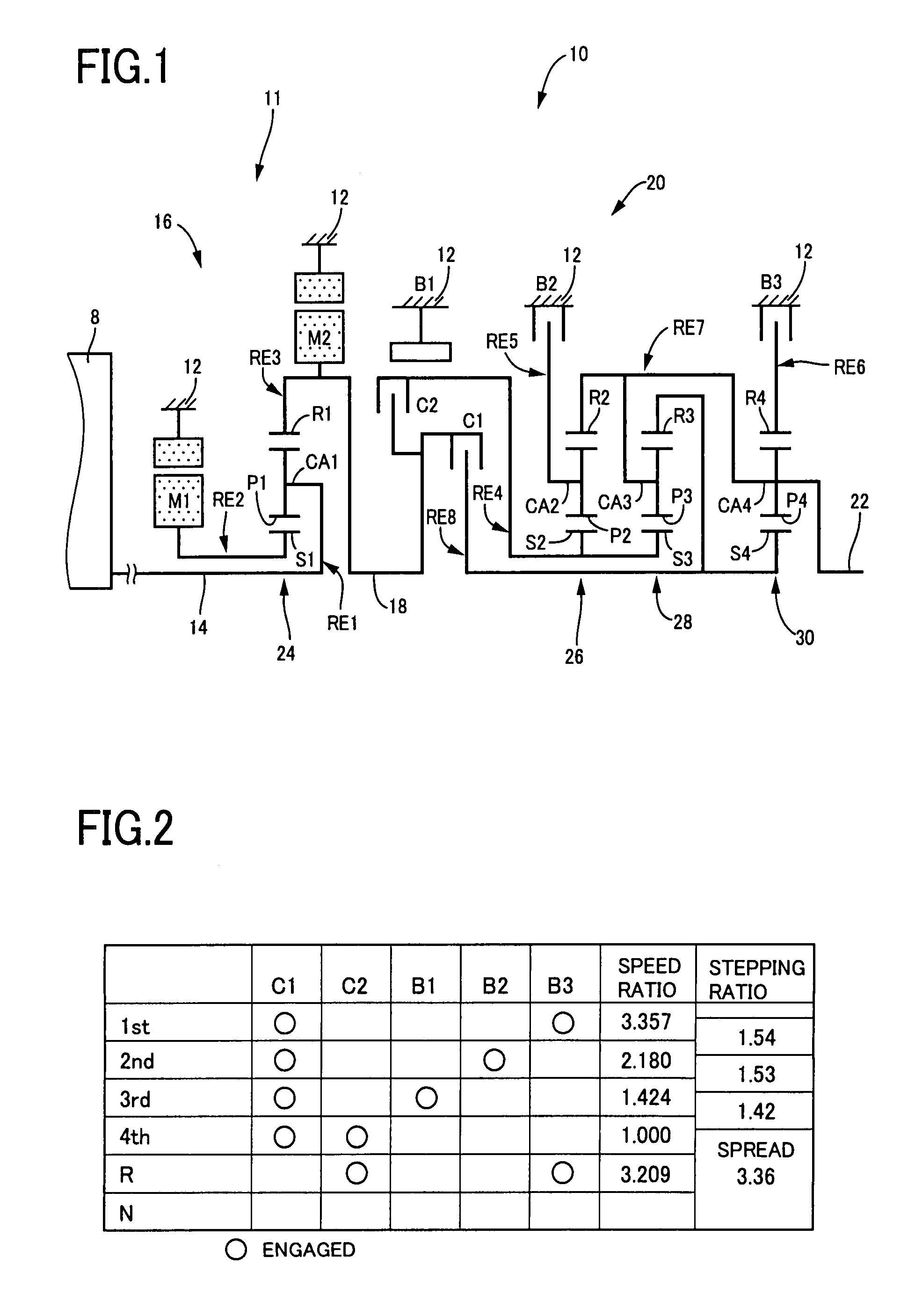
[0054]Referring to the schematic view of FIG. 1, there is shown a transmission mechanism 10 constituting a part of a drive system for a hybrid vehicle, which drive system is controlled by a control apparatus constructed according to this invention.

[0055]As shown in FIG. 1, the transmission mechanism 10 includes: an input rotary member in the form of an input shaft 14; a continuously-variable transmission portion in the form of an electric differential portion 11 connected to the input shaft 14 either directly, or indirectly via a pulsation absorbing damper (vibration damping device) not shown; a mechanical power transmitting portion in the form of an automatic transmission portion 20 disposed between the electric differential portion 11 and drive wheels 34 (shown in FIG. 7) of the vehicle, and connected in series via a power transmitting member 18 (power transmitting shaft) to the differential 11 and the drive wheels 34; and an output rotary member in the form of an output shaft 22 ...

second embodiment

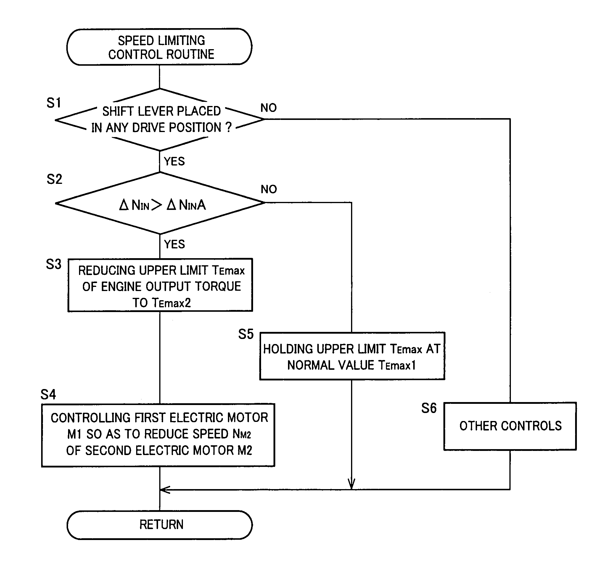
[0128]In the first embodiment, the upper limit value TEmax2 of the engine output torque TE is held constant. However, the upper limit value TEmax2 may change with the presently established speed ratio γ of the automatic transmission portion 20 such that the upper limit value TEmax2 decreases with an increase of the speed ratio γ. One-dot chain lines in FIG. 10 represent the upper limit values TEmax2 corresponding to the different speed ratio values γ of the automatic transmission portion 20. Alternatively, the upper limit value TEmax2 may change with the rotating speed NM2 of the second electric motor M2 such that the upper limit value TEmax2 decreases with an increase of the rotating speed NM2. Further alternatively, the upper limit value TEmax2 may decrease with an increase of the speed ratio γ and an increase of the rotating speed NM2.

third embodiment

[0129]In the first and second embodiments described above, the upper limit value TEmax of the output torque TE of the engine 8 is abruptly reduced from the normal value TEmax1 to the reduced value TEmax2, when the rotating-speed difference ΔNIN becomes larger than the threshold value ΔNINA, as indicated in FIG. 10. In the present third embodiment, however, the upper limit value TEmax continuously or gradually decreases with an increase of the rotating-speed difference ΔNIN, as indicated by one-dot chain lines in FIG. 12. Alternatively, the upper limit value TEmax may continuously or gradually decrease with an increase of the speed ratio γ of the automatic transmission portion 20. Further alternatively, the upper limit value TEmax2 may decrease with an increase of the rotating speed NM2 and an increase of the speed ratio γ. This embodiment permits a higher degree of stability to prevent the excessive rise of the rotating speed NM2 of the second electric motor M2.


PUM


Abstract

A control apparatus for a vehicular drive system including an electric differential portion and a mechanical power transmitting portion which are disposed in series in a power transmitting path between an engine and a drive wheel of a vehicle, the control apparatus being configured to limit an output of the engine according to a difference between an actual rotating speed of an input rotary member of the mechanical power transmitting portion, and a theoretical rotating speed calculated from an actual vehicle speed and a presently established speed ratio of the mechanical power transmitting portion, whereby reduction of torque capacity of an input clutch provided in the mechanical power transmitting portion does not cause an excessive rise of the rotating speed of a rotary member which is located on one side of the input clutch nearer to the engine, and an excessive rise of the rotating speed of an electric motor connected to the input rotary member.

Description

CROSS REFERENCE TO RELATED APPLICATION[0001]The present application claims priority from Japanese Patent Application No. 2006-304615, which was filed on Nov. 9, 2006, the disclosure of which I herein incorporated by reference in its entirety.BACKGROUND OF THE INVENTION[0002]1. Field of the Invention[0003]The present invention relates to a control apparatus for a vehicular drive system including an electric differential portion and a mechanical power transmitting portion which are disposed in series with each other in a power transmitting path between an engine and a drive wheel of a vehicle, and more particularly to techniques for limiting rotating speeds of input members of the mechanical power transmitting portion in the event of a failure of a coupling device of the mechanical power transmitting portion during running of the vehicle, and for thereby assuring high durability of those input members.[0004]2. Discussion of Prior Art[0005]There is known a vehicular drive system includ...

Claims


Application Information

Patent Timeline
Patent Type & Authority Patents(United States)
IPC IPC(8): G06G7/63B60W10/08B60K6/445B60K6/543B60K6/547B60L50/16B60W10/02B60W10/04B60W10/06B60W10/10B60W10/105B60W20/00F02D29/00F02D29/02
CPCB60K6/365B60K6/445B60W10/06B60W10/115B60W30/186B60K1/02B60W20/00Y10T477/6403B60W2510/0241F16H2037/0873Y02T10/6239Y10T477/6418Y10T477/347Y10T477/32Y02T10/62B60W20/30B60W10/02B60W10/10
Inventor MATSUBARA, TOORUTABATA, ATSUSHIMUTA, KOICHIROKAIFUKU, MASAKAZUKATOH, HIDENORINOMURA, TOMOKAZU
Owner TOYOTA JIDOSHA KK
Why Eureka
Try Eureka