
Device for producing a fiber preform with virtually any desired surface geometry by the TFP process

a fiber preform and fiber technology, applied in the direction of embroidering machines, automatic machines, textiles and paper, etc., can solve the problems of not being able to achieve the intended alignment of reinforcing fibers in the fiber preform, only guiding and laying fiber strands, and only partially achieving fiber strands

Inactive Publication Date: 2011-06-07
AIRBUS OPERATIONS GMBH
View PDF23 Cites 5 Cited by
  • Summary
  • Abstract
  • Description
  • Claims
  • Application Information

AI Technical Summary

Benefits of technology

[0008]It is one of the objects of the invention to provide a device for producing fiber preforms that allows fiber preforms to be produced with virtually any desired surface geometry, differing from the planar shape. The device according to the invention is additionally intended to necessitate only minor modifications to known devices for carrying out the TFP process.
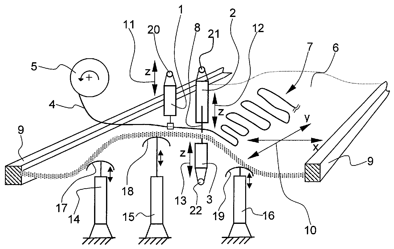
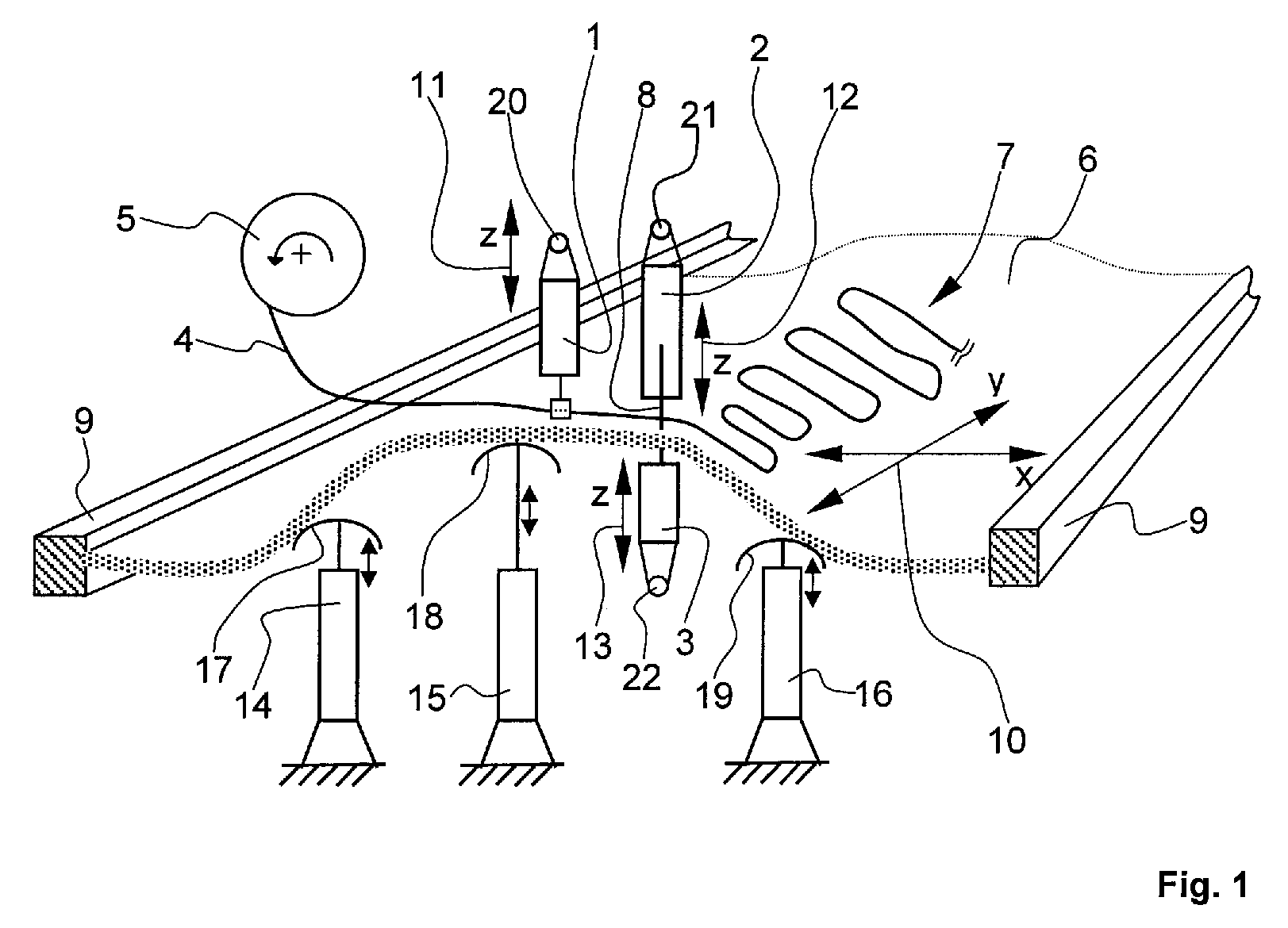
[0015]The fact that the backing layer can be positioned in a spatial xy direction in relation to the guiding device and the sewing head, wherein the sewing head and / or the guiding device can be positioned in a spatial z direction, makes it possible by means of the device according to the invention and the TFP process to produce a fiber preform which has virtually any desired surface geometry, in particular also a surface geometry differing from the planar shape, and in which moreover the reinforcing fibers are aligned substantially such that they are oriented with the flux of force. The device according to the invention in this case merely requires additional mobility of the sewing head in the spatial z direction, so that the already known devices for carrying out the TFP process can be converted or modified relatively easily.
[0018]A further embodiment provides that the backing layer is accommodated in a clamping frame. This allows the movement of the backing layer in the xy direction to be achieved in a simple way by corresponding movement of the clamping frame by means of actuators, controlled by an open-loop and closed-loop control device. If appropriate, in particular if there is inadequate elasticity of the backing layer, it may be required to vary the geometry of the clamping frame by means of actuators, in order to assist the variation of the surface geometry of the backing layer by the rams.
[0019]A further embodiment of the device according to the invention provides that the backing layer is formed by a sheet-like knitted fabric, in particular a woven fabric or the like, for the attachment of a fiber strand by the conventional method of attachment with an upper fixing thread and a lower fixing thread. This allows the conventional devices for carrying out the TFP process with an upper fixing thread and a lower fixing thread to continue to be used after a corresponding structural modification, in particular in the form of the additional positionability of the sewing head and the guidance of the lower thread in the z direction.
[0021]The use of a rubber sheet or a rubber mat allows attachment of the fiber strands in the so-called “tufting” process by means of the upper fixing thread alone, so that it is possible to dispense entirely with both the lower thread guide and the lower fixing thread. This provides a construction of the device according to the invention that is considerably simpler. The upper fixing thread is hereby introduced at least superficially into the rubber sheet and becomes bound in it on account of the high elasticity, so that, when the needle is pulled out, it forms a loop which is lodged in the region of the surface of the rubber sheet and ensures adequately secure attachment of the fiber strand, even without a backing layer in the sense of the conventional method of attachment with upper and lower fixing threads.

Problems solved by technology

A disadvantage of the known devices for carrying out the TFP process is that the fiber strand is only guided and laid in one plane, for example the xy plane.
However, the further processing of the initially planar fiber preform may cause undesired wave formations and displacements of the reinforcing fibers, so that the intended alignments of the reinforcing fibers in the fiber preform, in particular alignments oriented with the flux of force, are not achieved, or only partially.

Method used


Image

  • Device for producing a fiber preform with virtually any desired surface geometry by the TFP process
  • Device for producing a fiber preform with virtually any desired surface geometry by the TFP process

Examples


Embodiment Construction

[0023]FIG. 1 shows a perspective basic representation of the device according to the invention.

[0024]The device comprises a guiding device 1, a sewing head and a lower thread guide 3. A fiber strand 4 is drawn off continuously from a supply roll 5 and laid by the guiding device 1 on a backing layer 6 in virtually any desired path curve to form a fiber preform 7. Subsequently, the fiber strand is attached on the backing layer 6 by a needle 8 arranged at the sewing head 2. This involves using an upper fixing thread and a lower fixing thread that are not represented. The upper fixing thread and the lower fixing thread form underneath the backing layer 6 a multiplicity of loops, by means of which the fiber strand 4 is attached on the backing layer 6. The upper fixing thread is led through the needle 8 in the region of the sewing head 2, while the lower fixing thread is passed through the lower thread guide 3 underneath the backing layer 6. In order that the needle 8 can penetrate the ba...


PUM

PropertyMeasurementUnit
Flexibilityaaaaaaaaaa
Surfaceaaaaaaaaaa
Elasticityaaaaaaaaaa

Abstract

Device for producing a fiber preform with virtually any desired surface geometry by a TFP process. A guiding device lays a fiber strand along virtually any desired path curve on a backing layer and a sewing head attaches the fiber strand on the backing layer by at least one fixing thread. The backing layer can be positioned in an xy direction in relation to the guiding device and the sewing head, wherein the sewing head and / or the guiding device can be positioned in a z direction. The separation of the positioning capabilities of the backing layer (xy direction) and the guiding device, the sewing head and the lower thread guide (z direction) provides a relatively simple device construction. Example devices can produce fiber preforms for dome-shaped composite components for use inter alia as pressure bulkheads for cabins in aircraft with virtually optimum properties.

Description

FIELD OF THE INVENTION[0001]The invention relates to a device for producing a fiber preform with virtually any desired surface geometry by the TFP process, wherein a fiber strand can be laid by a guiding device in virtually any desired path curve on a backing layer and the fiber strand can be attached on the backing layer by at least one fixing thread by means of a sewing head.BACKGROUND OF THE INVENTION[0002]In lightweight construction, in particular in aircraft construction and in aerospace, fiber-reinforced composite components, which have a high weight-saving potential on account of their high strength with at the same time low mass, are increasingly being used for load-bearing structural components.[0003]The alignment of the reinforcing fibers in the finished composite component has a decisive influence on the achievable rigidity and strength. The reinforcing fibers should, as far as possible, follow the direction of loading, not have any wave formations and be subjected to uni...

Claims


Application Information

Patent Timeline
IPC IPC(8): D05B3/12D05B39/00
CPCB29B11/16B29C70/086B29C70/382B29L2031/3082B29C70/48
Inventor JOERN, PAULEBERTH, ULRICH
Owner AIRBUS OPERATIONS GMBH
Learn More