Pedal simulation device

a simulation device and pedal technology, applied in mechanical control devices, brake systems, controlling members, etc., to achieve the effect of reducing damping, high resistance, and reducing hysteresis

Active Publication Date: 2011-06-07
LUCAS AUTOMOTIVE GMBH
View PDF11 Cites 5 Cited by
  • Summary
  • Abstract
  • Description
  • Claims
  • Application Information

AI Technical Summary

Benefits of technology

[0010]The vacuum that builds up in the working chamber upon actuation of the brake pedal is dependent on the behavior of the modeling device and is reducible by means of a fluid flowing through the modeling device. Because of the preferably relatively small (dead) volume of the working chamber at the start of actuation of the pedal, this vacuum may assume a relatively large value within a relatively short time of the pedal actuation, i.e. after a relatively short actuating distance, so that the pedal simulation device responds rapidly. The modeling device then allows only a limited replenishing flow of fluid into the working chamber, with the result that the pedal is actuable only with appropriate resistance. Upon release of the pedal, the pedal is returned to its normal position by the resetting element, which may be of any desired configuration, wherein this resetting movement is likewise influenceable by the modeling device.
[0014]Furthermore, in a development of the invention the modeling device may comprise a bypass channel that bypasses the throttle channel. It is therefore possible that, upon a release of the pedal after actuation thereof, under the action of the resetting element fluid flows out of the working chamber through the bypass channel. This means that an actuation of the pedal is counteracted by an appropriately high resistance owing to the throttle device but that, upon release of the pedal after prior actuation, the throttle device may be substantially bypassed so that the resetting movement may be effected with markedly weakened damping and hence ultimately faster. A hysteresis is therefore imposed on the pedal movement. This may be achieved, for example, in that the by-pass channel has a non-return valve that allows fluid to pass substantially unimpeded out of the working chamber and prevents fluid from passing into the working chamber. The use of a non-return valve has the advantage that it is a relatively simple and hence inexpensively available, operationally reliable component.

Problems solved by technology

The modeling device then allows only a limited replenishing flow of fluid into the working chamber, with the result that the pedal is actuable only with appropriate resistance.

Method used


Image

  • Pedal simulation device
  • Pedal simulation device
  • Pedal simulation device

Examples


first embodiment

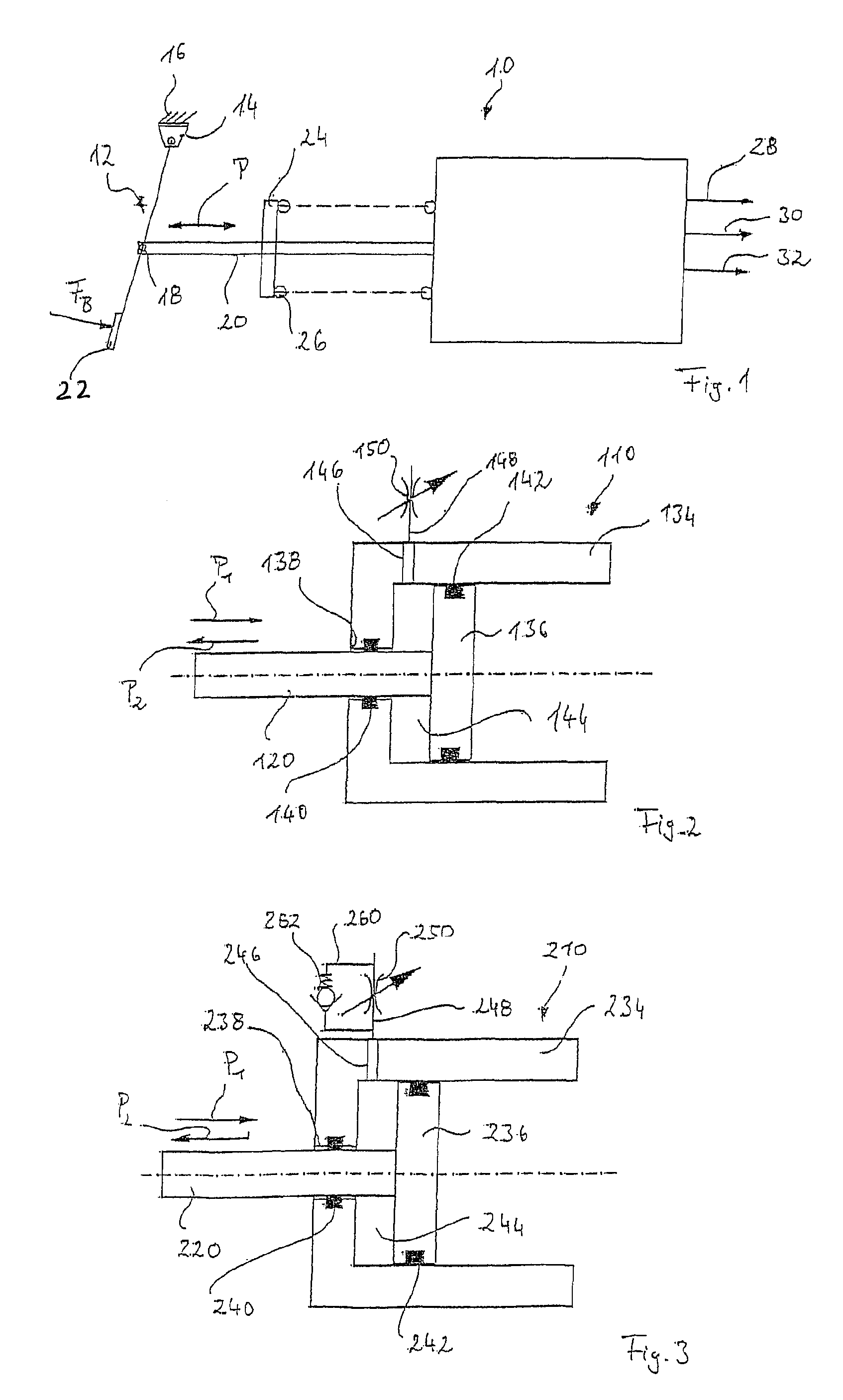
[0032]The first embodiment shown in FIG. 2 shows a pedal simulation device 110 comprising a cylinder 134, which is open at one end and has a working piston 136 guided therein. The working piston 136 is coupled to the actuating rod 120 for joint movement. The actuating rod 120 extends through an axial opening 138, wherein in the axial opening a sealing ring 140 is disposed. The effect achieved by the sealing ring 140 is that the actuating rod 120 may be moved axially back and forth in a fluid-tight manner inside the axial opening 138, as is represented in FIG. 2 by arrow P.

[0033]A sealing ring 142 is provided also at the peripheral surface of the working piston 136 facing the inner wall of the cylinder 134, so that the working piston 136 may also be moved back and forth in a fluid-tight manner inside the cylinder 134 together with the actuating rod 120.

[0034]The cylinder 134 together with the working piston 136 and the actuating rod 120 therefore enclose an annular working chamber 14...

second embodiment

[0045]In operation, the pedal simulation device 210 according to FIG. 3 therefore behaves differently to the pedal simulation device 110 according to FIG. 2 in that, upon a resetting movement of the actuating rod 220 and hence of the working piston 236 in accordance with arrow P2, the air contained in the working chamber 244 may pass substantially unimpeded into the ambient atmosphere, wherein the throttle device 250 is bypassed by means of the bypass line 260. This means that the brake pedal 12 may move under the action of the spring 26 and substantially without damping by the throttle device 250 relatively quickly into its normal position. On the other hand, the throttle device 250 in the second embodiment according to FIG. 3 acts in the same way as the embodiment according to FIG. 2 because, when air from the ambient atmosphere is taken into the working chamber 244, the non-return valve 262 closes and prevents a flow of air through the bypass line 260.

third embodiment

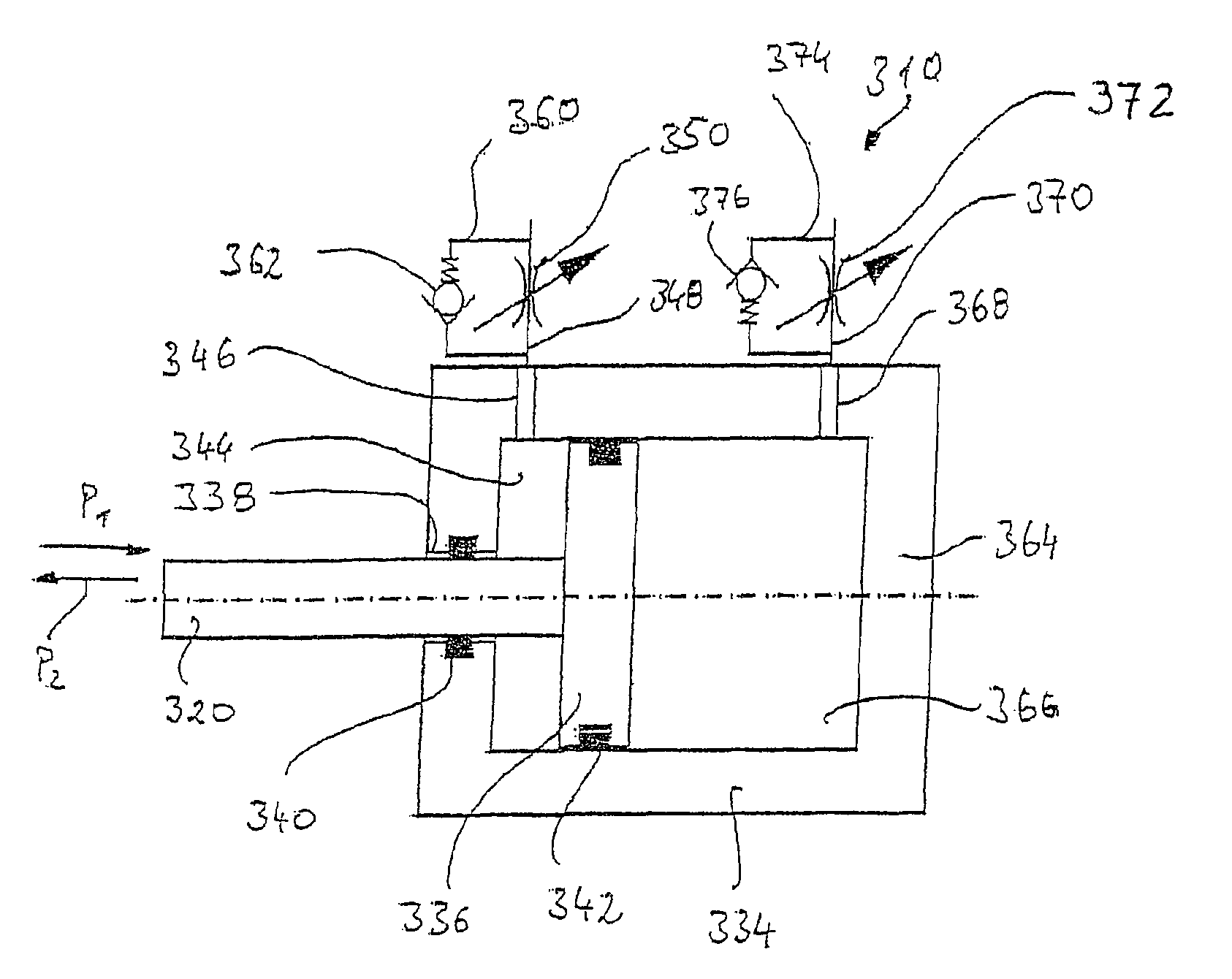
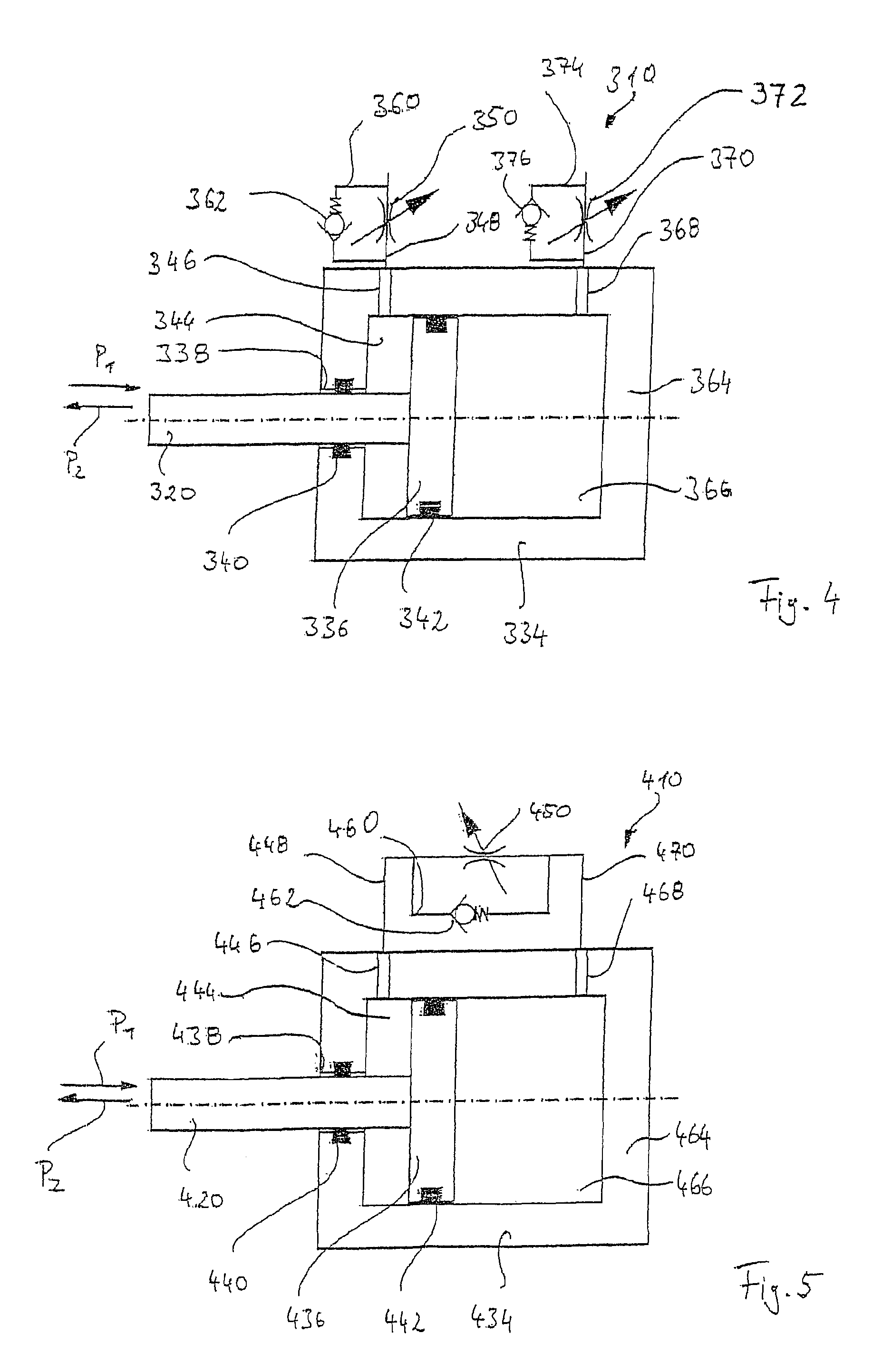
[0046]FIG. 4 shows the pedal simulation device 310 according to the invention. The same reference characters are used for the identical or equivalent components as with regard to FIGS. 1 to 3, only with the number “3” placed in front.

[0047]The third embodiment according to FIG. 4 differs from the second embodiment according to FIG. 3 in that the cylinder 334 is no longer open at one end but is closed at its end remote from the actuating rod 320 by the end wall 364. In the cylinder 334 there is therefore, in addition to the working chamber 344, a complementary working chamber 366 that is delimited at one end by the working piston 336. Opening into this complementary working chamber 366 close to the end wall 364 is a further radial opening 368. The radial opening 368 communicates with a fluid line 370, which comprises, on the one hand, a throttle channel with an adjustable throttle device 372 and, on the other hand, a bypass channel 374 with a non-return valve 376. The non-return valv...


PUM


Abstract

The invention relates to a pedal simulation device for simulating the reaction behavior of a pedal, in particular of a brake pedal of a vehicle brake system, comprising a cylinder, a piston disposed displaceably inside the cylinder and coupled to the pedal and delimiting a working chamber inside the cylinder, a resetting element which, upon an actuation of the pedal, exerts a resetting force on the pedal, and a modelling device, which is fluidically connected to the working chamber, for influencing the reaction behavior of the pedal. In the invention, for achieving the reaction behavior it is provided that, upon an actuation of the pedal, by means of the modelling device a vacuum, which is arising or has arisen in the working chamber, is built up.

Description

CROSS REFERENCE TO RELATED APPLICATIONS[0001]This application is a continuation of U.S. patent application Ser. No. 11 / 151,142, filed Jun. 13, 2005 which is a continuation of International Application No. PCT / EP03 / 13583 filed Dec. 2, 2003, and which claimed priority to German Patent Application No. 102 60 008.2 filed Dec. 13, 2002, the disclosures of all of which are incorporated herein by reference.BACKGROUND[0002]The invention relates to a pedal simulation device for simulating the reaction behavior of a pedal, in particular of a brake pedal of a vehicle brake system, comprising a cylinder, a piston disposed displaceably inside the cylinder and coupled to the pedal and delimiting a working chamber inside the cylinder, a resetting element capable of exerting a resetting force on the pedal, and a modeling device, which is fluidically connected to the working chamber, for influencing the reaction behavior of the pedal.[0003]Such pedal simulation devices are already used in vehicles w...

Claims


Application Information

Patent Timeline
Patent Type & Authority Patents(United States)
IPC IPC(8): B60T13/66B60T7/04B60T17/00G05G1/30
CPCB60T7/042G05G1/30B60T17/00Y10T74/20528
Inventor GIERING, WILFRIEDMICHELS, ERWINOHLIG, BENEDIKTSTEINHEUER, HERBERT
Owner LUCAS AUTOMOTIVE GMBH
Why Eureka
Try Eureka