Manipulator

a technology of manipulators and fixing parts, which is applied in the field of manipulators, can solve the problems of affecting the sensitivity and errors of sensors, and it is difficult to increase the utilization rate of manipulators, so as to achieve the effect of simple recovery of the cleanness of the end effector part and short period of time, increasing the size of the fixing member

Active Publication Date: 2011-06-07
KK TOSHIBA
View PDF5 Cites 10 Cited by
  • Summary
  • Abstract
  • Description
  • Claims
  • Application Information

AI Technical Summary

Benefits of technology

[0009]In view of the aforementioned circumstances, an object of the present invention is to provide a manipulator capable of recovering cleanness of an end effector part simply and in a short period of time.
[0010]A manipulator of the present invention includes an end effector that performs a mechanical work on a work subject; a support member that supports the end effector; an expandable and contractible fixing member provided to the support member and having a first space; and first fluid supply means for supplying fluid to the first space. The manipulator is configured to fix a flexible cover for covering the end effector to the support member by supplying the fluid to the first space to increase a size of the fixing member.
[0011]According to the present invention, it is possible to provide a manipulator capable of recovering cleanness of an end effector part simply and in a short period of time.

Problems solved by technology

Moreover, since a work using the manipulator is impossible during the cleaning thereof, it is difficult to increase the utilization rate of the manipulator when highly clean work should be performed therewith.
Furthermore, even when highly clean work need not be performed with the manipulator, if a work subject is deposited and accumulated on a sensor used for controlling the end effector part, such as a contact sensor for detecting a contact state between the end effector and the work subject, this might affect sensitivity and errors of the sensor.

Method used


Image

  • Manipulator
  • Manipulator
  • Manipulator

Examples


first embodiment

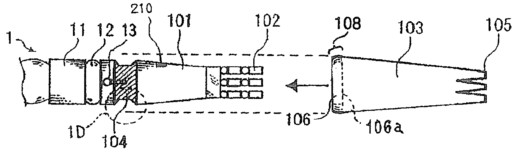
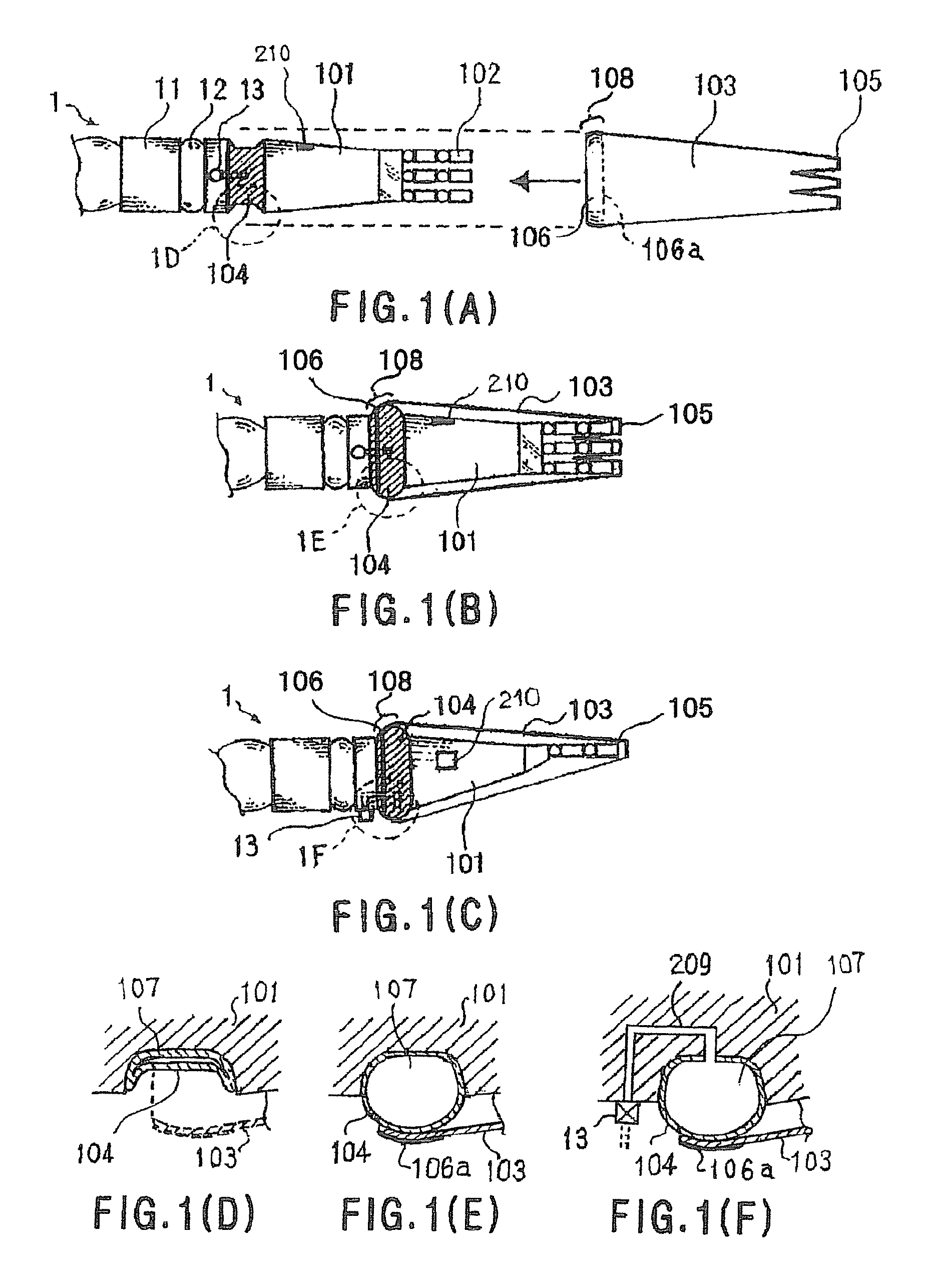
[0027]FIGS. 1A to 1F show a first embodiment of a manipulator according to the present invention.

[0028]A manipulator 1 includes a support member 101 and an end effector 102 supported by the support member 101 with respect to a robot arm 11.

[0029]The arm 11 is part of a revolute robot arm provided on an unillustrated robot caused to perform a predetermined work on a work subject.

[0030]The support member 101 is provided at a tip portion of the arm 11 and is physically connected to the arm 11 and the end effector 102. A movable part 12 is provided between the arm 11 and the support member 101. The movable part 12 is provided to rotate the end effector 102 around an axis of a longitudinal direction of the arm 11. A marker 210 used for operating a dispenser to be described later is attached to a side surface of the support member 101.

[0031]The end effector 102 is a robot hand having multiple bendable and stretchable finger members. The end effector 102 is configured to perform a predeter...

second embodiment

[0058]FIGS. 6A to 6B show a second embodiment of a manipulator according to the present invention.

[0059]A manipulator 3 of the present embodiment is one in which a function of detaching the flexible cover 103 from the end effector 102 is added to the manipulator 1 of the first embodiment.

[0060]The following will explain the details with reference to FIGS. 6A and 6B.

[0061]The support member 101 is provided with a valve 602. The valve 602 communicates with the first space 107 through the passage 601. The valve 602 is provided in such a manner that a fluid (air) supplied to the first space 107 is discharged when the valve 602 is opened.

[0062]Moreover, the valve 602 is provided for the fluid discharged by opening the valve 602 in order to be discharged to a second space 604 between the end effector 102 and the flexible cover 103 through a passage 601.

[0063]By changing the valve 602 from its closed state to its open state, at least part of the fluid supplied to the first space 107 is mov...

third embodiment

[0066]FIGS. 7A to 1C show a third embodiment of a manipulator according to the present invention.

[0067]A manipulator 4 of the present embodiment is one in which a function of detecting that an object 901 contacts a portion covered with the flexible cover 103 is added to the manipulator 1 of the first embodiment.

[0068]The following will explain the details with reference to FIGS. 7A to 11.

[0069]At least part of the support member 101 and the end effector 102 are covered with an inner cover 706. The same material as that of the flexible cover 103 is used for the inner cover 706. It should be noted that the material of the inner cover 706 does not have to be the same as that of the flexible cover 103, and can be properly selected according to the purpose of use. However, the inner cover 706 is stopped and fixed at a middle part of the tapered support member 101 with the circumference of an opening of the inner cover 706, and therefore it is better to use material having higher elastici...


PUM


Abstract

A manipulator includes an end effector, a support member that supports the end effector, and a fixing member provided to the support member and made of a tube-shaped flexible film with a space therein. In the manipulator, a fluid is supplied to the space of the fixing member to inflate the fixing member so that a flexible cover for covering the end effector is fixed to the support member. Accordingly, cleanness of the end effector is restored.

Description

CROSS REFERENCE TO RELATED APPLICATIONS[0001]The present application is based on and claims priority from Japanese Patent Application No. 2007-226992, filed on Aug. 31, 2007, the disclosure of which is hereby incorporated by reference herein in its entirety.BACKGROUND OF THE INVENTION[0002]1. Field of the Invention[0003]The present invention relates to a manipulator.[0004]2. Description of the Related Art[0005]A manipulator is used in a hospital, a nursing-care facility, a restaurant, home, etc. When an intended work is performed with a manipulator, a work subject such as chemicals, food or the like is sometimes deposited on an end effector part of the manipulator, and thus the end effector part might require cleaning, as described in Japanese Patent Application Publication No. 2005-279101.[0006]However, the manipulator described in Japanese Patent Application Publication No. 2005-279101 has many movable parts and thus needs to have a structure to facilitate cleaning when highly cle...

Claims


Application Information

Patent Timeline
Patent Type & Authority Patents(United States)
IPC IPC(8): B25J19/00
CPCB25J15/0009B25J19/0079Y10T74/20305Y10T74/20335
Inventor SUGAHARA, ATSUSHINAKAMOTO, HIDEICHIYOSHIMI, TAKASHI
Owner KK TOSHIBA
Why Eureka
Try Eureka